Application Options
The Application Options window holds the settings that apply to the software itself rather than to a single project — how the 3D window is drawn, how the pick tool behaves, and how updates are handled. Changes here affect every project you open.
Where to Find the Options
In the Project Items Tab, click the Application Options text and go to the Performance Options section in the properties panel. Or from the Project menu, select Options and then choose the Application tab at the top of the window that opens. Changes here apply to the main 3D window and affect how every project is displayed, not just the current one.
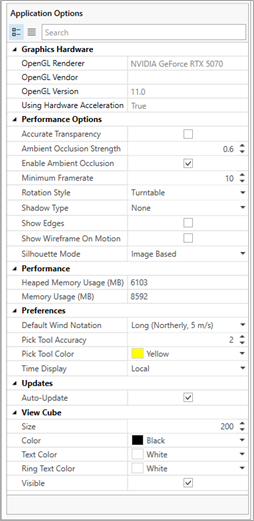
The 3D display controls in the Performance Options section of Application Options for in:Flux - Detect3D will be similar but with changes in the Preferences section
Graphics Hardware
The 3D window requires OpenGL 3.3 support. On capable hardware the rebuilt window runs at higher frame rates than previous versions. Text here shows which graphics card the software is currently using, the version of OpenGL and if Hardware Acceleration is turned on. To edit these settings, consult your graphics card settings menu.
Performance Options
The main 3D window was rebuilt in version 5.0 of in:Flux and version 3.0 of Detect3D, with improved lighting and higher frame rates. This section controls how it is drawn and how it behaves while you navigate. None of these settings change your model — they affect only how it is displayed, not the underlying geometry, calculation or results.
-
Accurate Transparency (off by default) — controls how the 3D window renders overlapping transparent surfaces, such as monitor regions, isosurfaces, risk datasets, fire zones, FOVs/FOIs.
-
With it OFF, transparent surfaces are rendered in the order they were added to the current view, meaning whichever item was displayed last appears in front of the others regardless of its actual position. This is the faster option and is fine for most work.
-
With it ON, only the outline of each transparent item is displayed. The transparent surfaces are drawn while you move the view with the mouse, then return to outlines once you stop. This makes it easier to maneuver around complex geometry without transparent results obscuring what sits behind them.
-
-
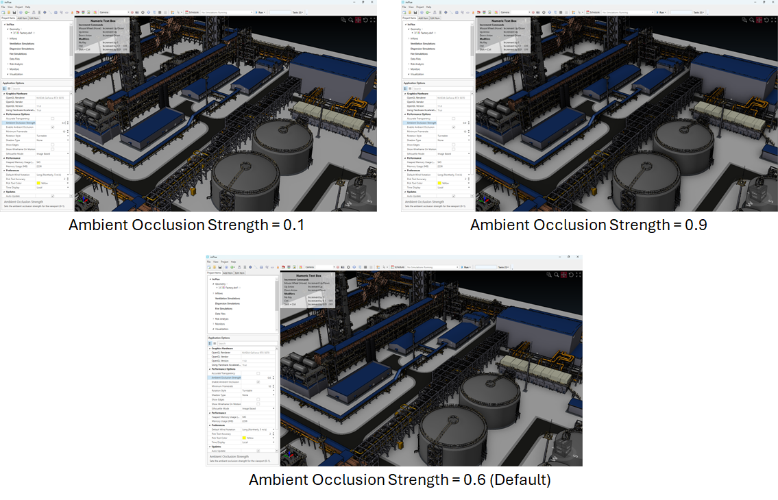
Ambient Occlusion Strength (default 0.6) sets how pronounced the shading is — raise it to deepen the effect, lower it to soften it, see examples below.
-
Enable Ambient Occlusion (on by default) — adds soft contact shadows where surfaces meet, in corners, and in recesses. This gives a strong sense of depth and makes congested geometry such as pipe racks and equipment modules much easier to read.
-
Minimum Framerate (default 10) - Sets the minimum framerate for the 3D window. To maintain it, some items are hidden while the view is being moved, then redrawn once movement stops.
-
Rotation Style - Sets how the 3D window responds to mouse rotation.
-
Turntable (default) - rotation is constrained so the model's vertical axis stays upright
-
Trackball - the model rotates freely in any direction
-
-
Shadow Type — casts shadows from the scene lighting, reinforcing the three-dimensional relationship between objects and the ground:
-
None (default) — no shadows.
-
Planar — shadows projected onto the ground plane; a lighter-weight option.
-
Realistic — full shadow rendering for the most natural result, at a higher rendering cost.
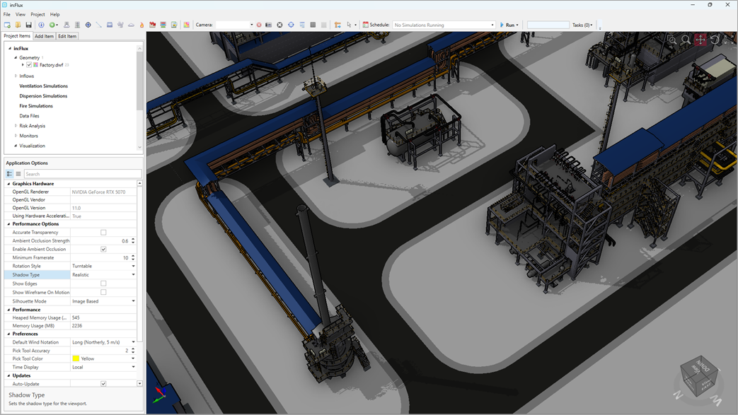
Realistic Shadow Type applied to the image above
-
-
Show Edges (off by default) - Sets whether the edges of geometry faces are outlined in the 3D window
-
Show Wireframe on Motion (off by default) - when on, the 3D window switches to wireframe (without displaying any solid surfaces) when any camera motion is detected, then returns to the full view when motion stops. Turn this opion on if you have a descrete graphics cards or if there is noticable delay in rendering of the 3D window when maneuvering around objects.
-
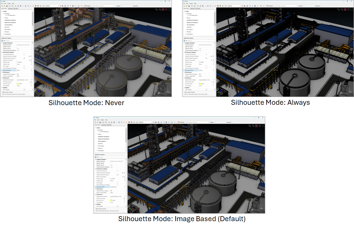
Silhouette mode — draws outlines around objects to emphasize their edges, so items stand out against a busy background:
-
Image Based (Default) — outlines are rendered using an image-space method; the standard balanced setting.
-
Always — outlines are drawn on every frame, including while you rotate or pan.
-
Last Frame — outlines are drawn once the view has settled rather than during interaction, which is lighter on frame rate while moving.
-
Never — outlines are turned off.
-
Performance
The Performance section is a read-only readout of how much memory the software is currently using. It is useful when reporting a performance problem to support.
-
Heaped Memory Usage (MB) — memory currently allocated on the heap.
-
Memory Usage (MB) — total memory currently used by the software.
Preferences (in:Flux)
-
Default Wind Notation (default Long) — sets how wind direction and speed are written throughout the software, for example Northerly, 5 m/s in long form.
-
Pick Tool Accuracy (default 2) — the number of decimal places shown by the pick tool.
-
Pick Tool Color (default Yellow) — sets the color used by the pick tool in the 3D window. Change it if the default does not stand out against your geometry.
-
Time Display (default Local) — sets whether times are shown in local time or UTC.
Preferences (Detect3D)
-
Always Show Default Model (default on) — sets whether the Insight Numerics default field of view is listed in the flame detector dropdown menus.
-
Auto-Show FOV (default off) — sets whether a detector's field of view (FOV) or field-of-influence (FOI) is displayed automatically when the detector is added to the project.
-
Azimuth System (default Clockwise from North) — sets the convention used for azimuth angles, either Clockwise from North or Counter-Clockwise from East. See Setting Project North.
-
Default Opacity (default 200) — sets the opacity applied to contours and isovolumes.
-
Pick Tool Accuracy (default 2) — the number of decimal places shown by the pick tool.
-
Pick Tool Color (default Yellow) — sets the color used by the pick tool in the 3D window. Change it if the default does not stand out against your geometry.
Updates
-
Auto-Update (on by default) — when on, the software checks for new versions automatically and prompts you when one is available.
View Cube
The view cube is the orientation widget shown in the lower-right corner of the 3D window for in:Flux or upper-right corner for Detect3D. It indicates which way the model is currently facing, and can be used to snap the view to a standard orientation.
-
Color (default Black) — sets the color of the cube itself.
-
Ring Text Color (default White) — sets the color of the compass lettering on the ring around the cube.
-
Size (default 200) — sets how large the cube is drawn in the corner of the 3D window.
-
Text Color (default White) — sets the color of the lettering on the cube faces.
-
Visible (on by default) — sets whether the view cube is shown in the 3D window at all. Turn it off to keep the corner of the view clear for screenshots.
Getting the Best Performance
-
The 3D window requires OpenGL 3.3 support. On capable hardware the rebuilt window runs at higher frame rates than previous versions.
-
Richer visuals trade against frame rate. If performance drops on a large model or on older hardware, lower the Ambient Occlusion Strength, set Shadow Type to None, set Silhouette Mode to Never or Last Frame, and turn on Show Wireframe On Motion. Each option is independent, and changing any of them affects only the display — never the model or the calculation results.
When to Use Them
-
Out of the box — ambient occlusion is already on (strength 0.6) and silhouettes are set to Image Based, giving good depth and edge definition on congested models, while accurate transparency and shadows are off. For most day-to-day work the defaults are a good balance.
-
For report and presentation images — set Shadow Type to Planar or Realistic and consider raising the Ambient Occlusion Strength for the most polished, clearly three-dimensional images. Leave Accurate Transparency off so transparent results are captured as full surfaces rather than outlines.
-
For navigating congested models — turn Accurate Transparency on. Reducing transparent items to outlines while the view is stationary lets you see the geometry behind them and makes it much easier to work your way around a busy scene.