Quick Box or Plane
The Quick Box option can be used to create boxes, walls, or ground pieces with ease. Several features within Detect3D and in:Flux can utilize the Quick Box feature to define cuboid type shapes: zones, sub-zone, monitor regions, etc. The Quick Box
Tool for these features appears as a red arrow - ![]()
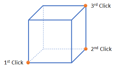
The Quick Box is defined by three clicks as shown below: 1st click is the starting coordinate, 2nd click is the width and length, and 3rd click is the height. After selecting the three defining points the associated coordinates will be entered in the Point 1 and Point 2 text boxes where applicable.
The following images will go over creating a ground object (planar surface) and two walls using the Quick Box feature:
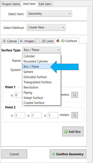
From the 3D Surfaces tab, choose the 'Box / Plane' option
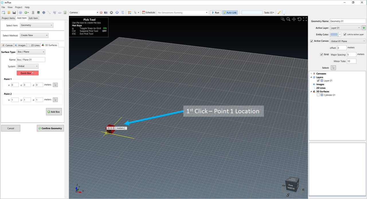
Click the red 'Quick Box' button to activate the tool. The first point selected will act as one of the two outer bounds for the plane
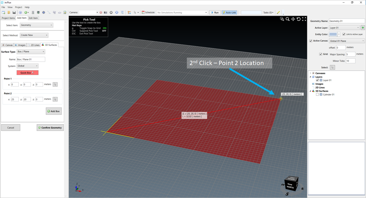
The second point selected will define the extents (length and width) of the box or plane to be defined.
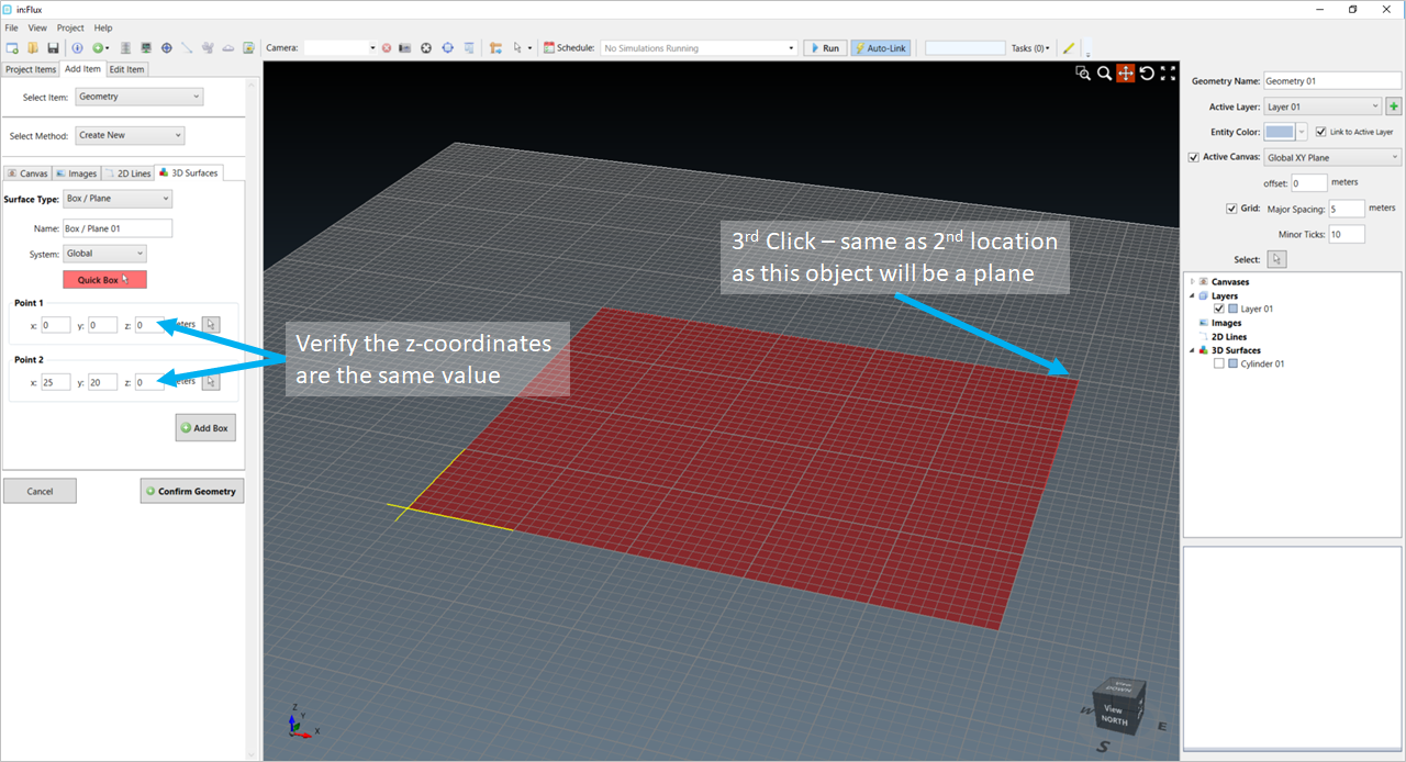
For planes or ground pieces, select the second point again (as the 3rd point) and ensure that the recorded height (z-coordinates) are the same
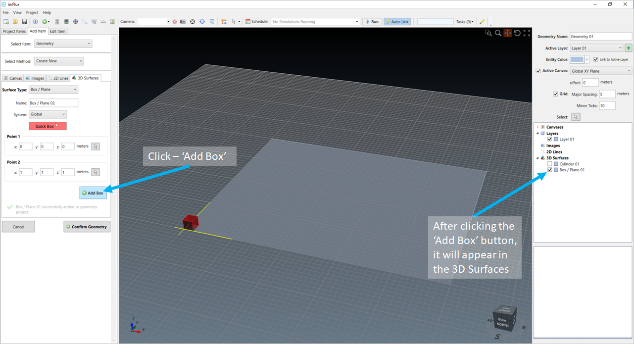
Click the 'Add Box' button to add the plane to the right-hand panel
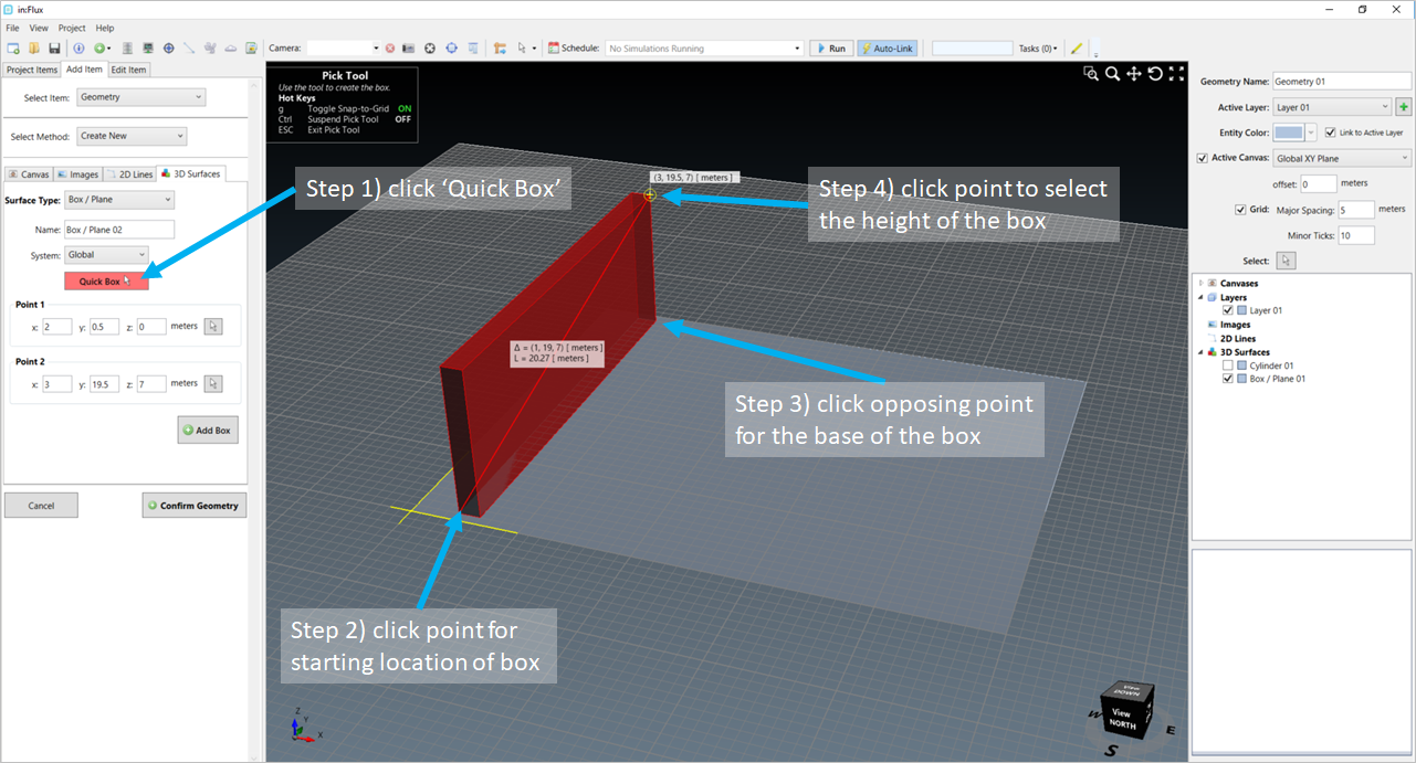
This process can be repeated for creating boxes. The above image shows the process for a wall to be created. Note that the 3rd click here is defining the height of the wall.
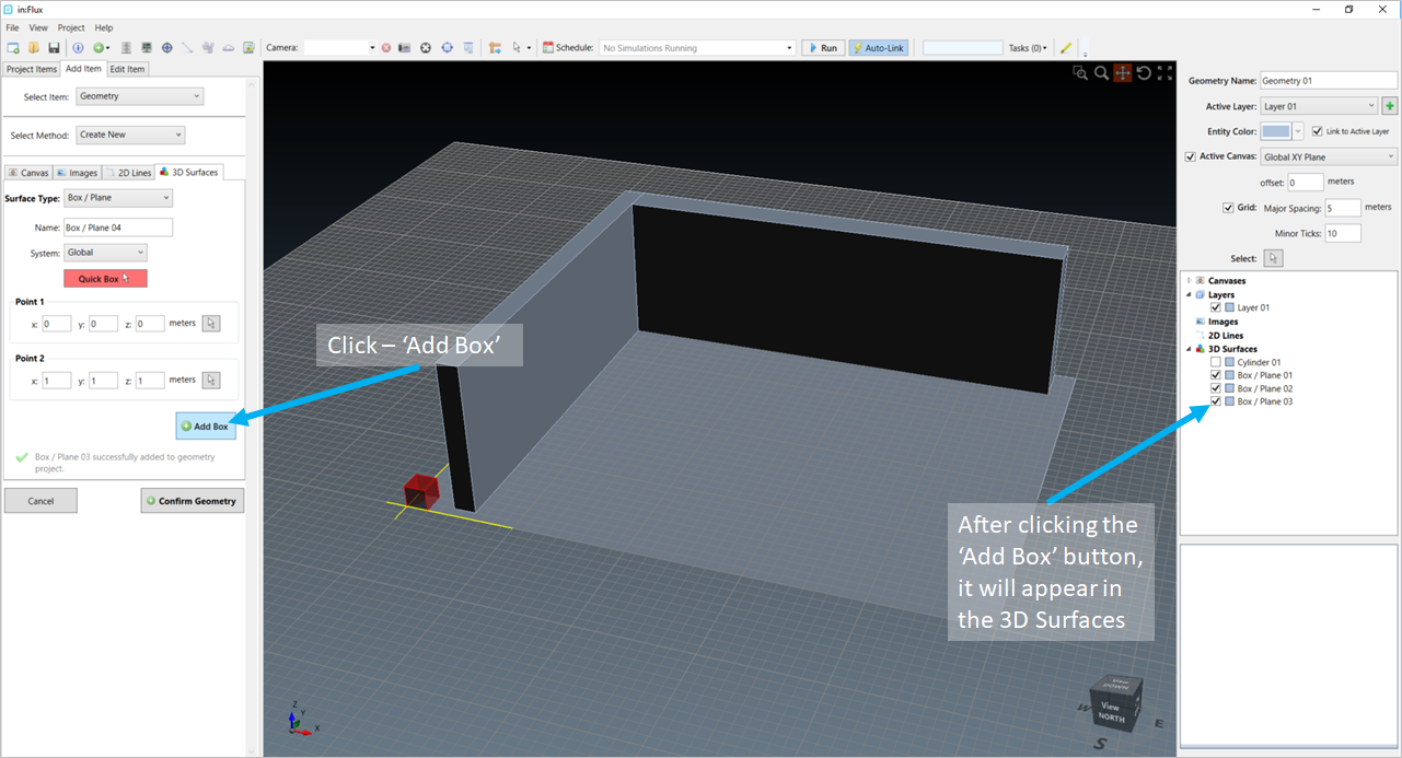
Be sure to always click the 'Add Box' button to add the 3D surface to the CAD Creation Project. You may also opt to enter coordinates of the box manually rather than use the 'Quick Box' tool.
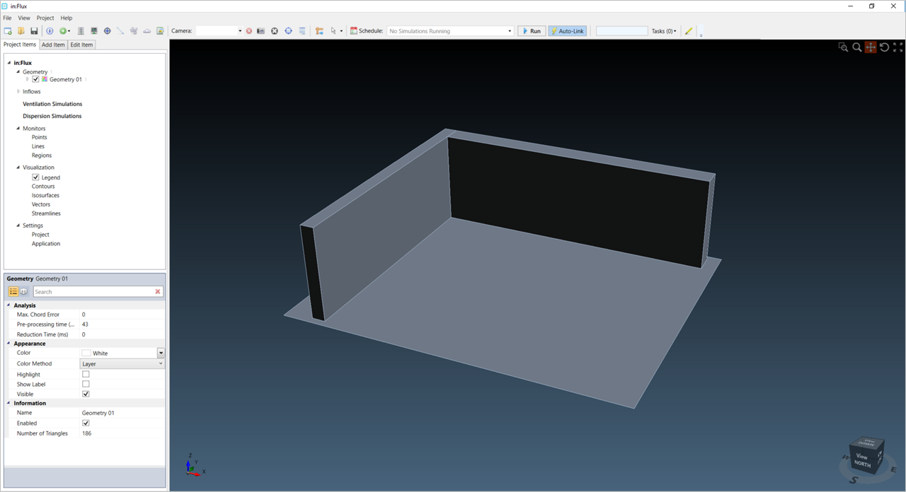
Note that any CAD created in the above interface will not be properly accounted for unless the  button is clicked. Upon selection, the normal
Detect3D or in:Flux interface will appear (as shown below) and the CAD can be used for future analyses. Any simulations or calculations already completed will need to be recalculated to properly include the created CAD geometry.
button is clicked. Upon selection, the normal
Detect3D or in:Flux interface will appear (as shown below) and the CAD can be used for future analyses. Any simulations or calculations already completed will need to be recalculated to properly include the created CAD geometry.