Importing Layout Drawings
How to import plot plan layout drawings:
1. Convert the page from pdf to an image format (jpg or png) by using a screenshot tool.
2. Load your project, right-click on Geometry and select “Create New Geometry”
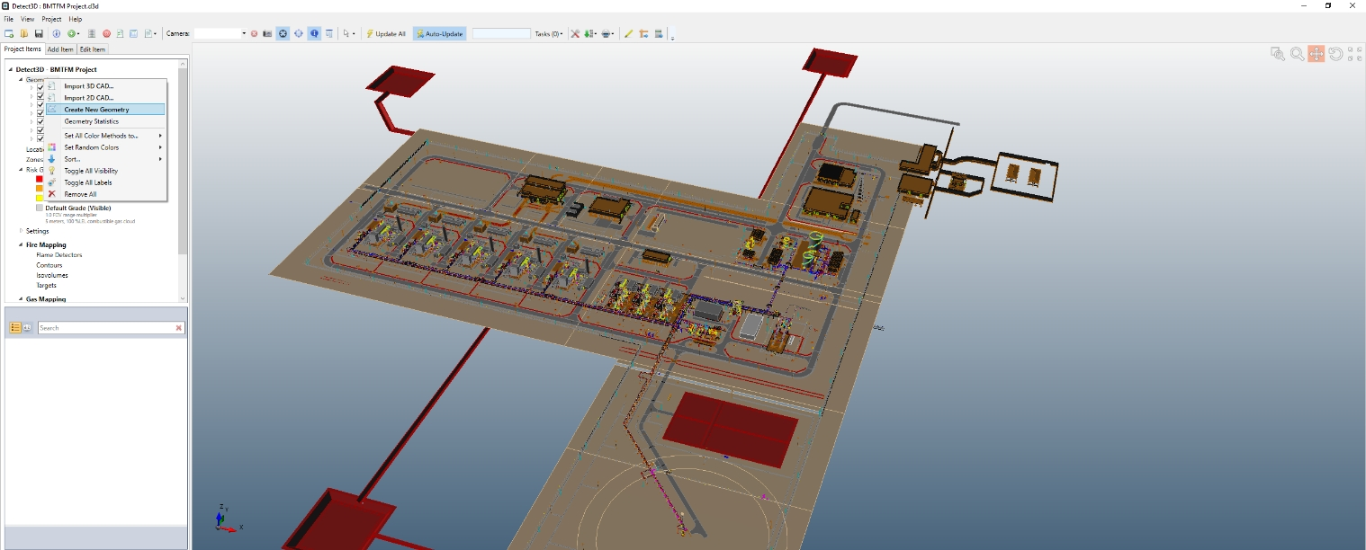
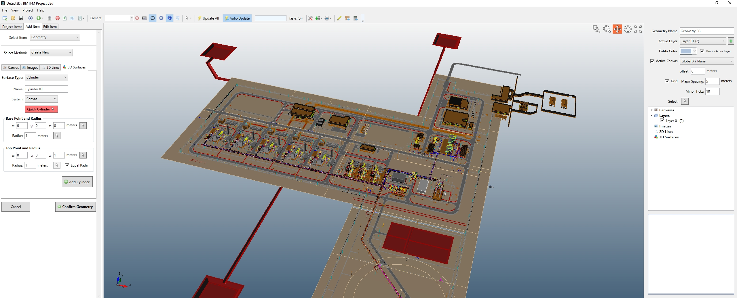
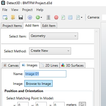
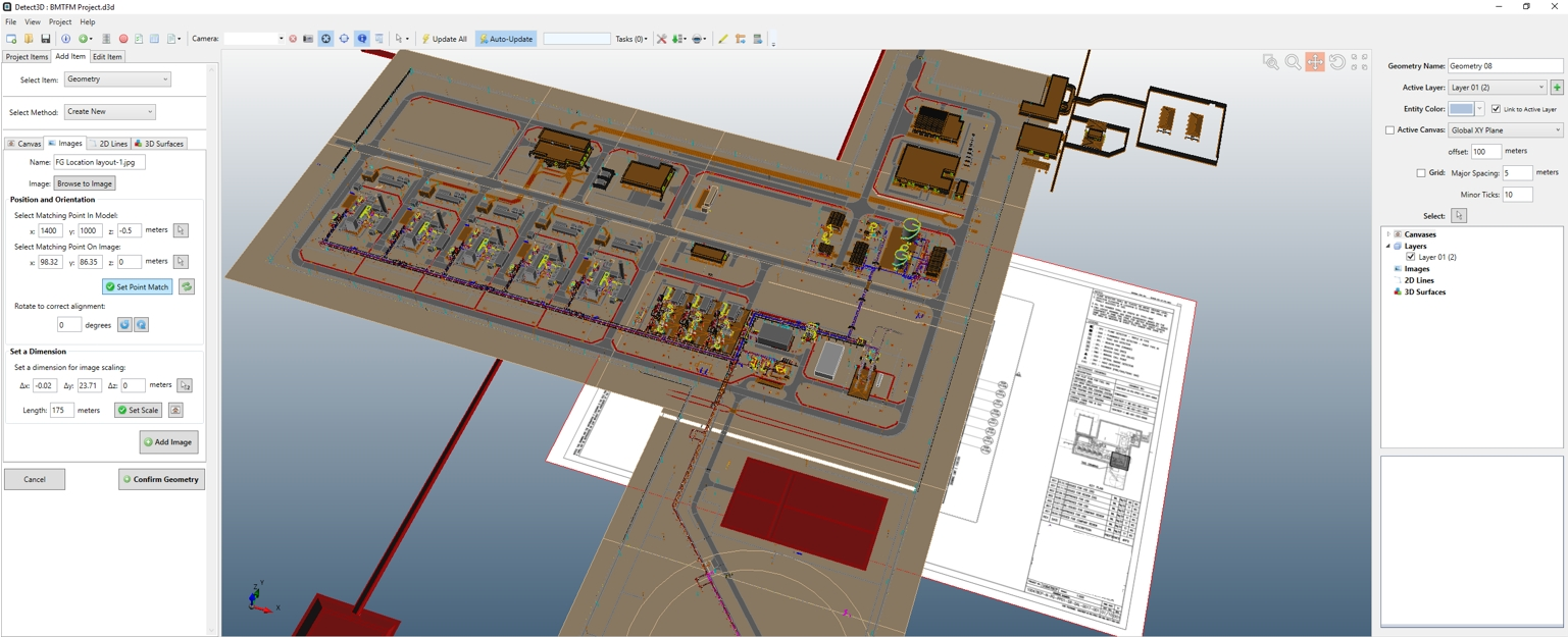
3. The CAD Creation Tool user interface, shown below, will appear. This is where you can add shapes, delete entities, and add images etc.
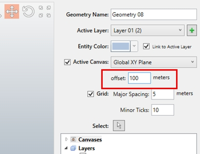
4. The first thing to get right is the “Drawing canvas”. This defines the plane that we are going to work on. For this example, the ground level for this CAD geometry is at about z = 100 meters, so select the offset (top right) to be 100 meters.
5. Next, on the left side select “Images”, click browse, and navigate to your saved image.
6. The image will be imported, but it will be a long way from the model – this is because the software doesn’t know the real location or the size of the contents of the image. If you zoom out, you will be able to see it.
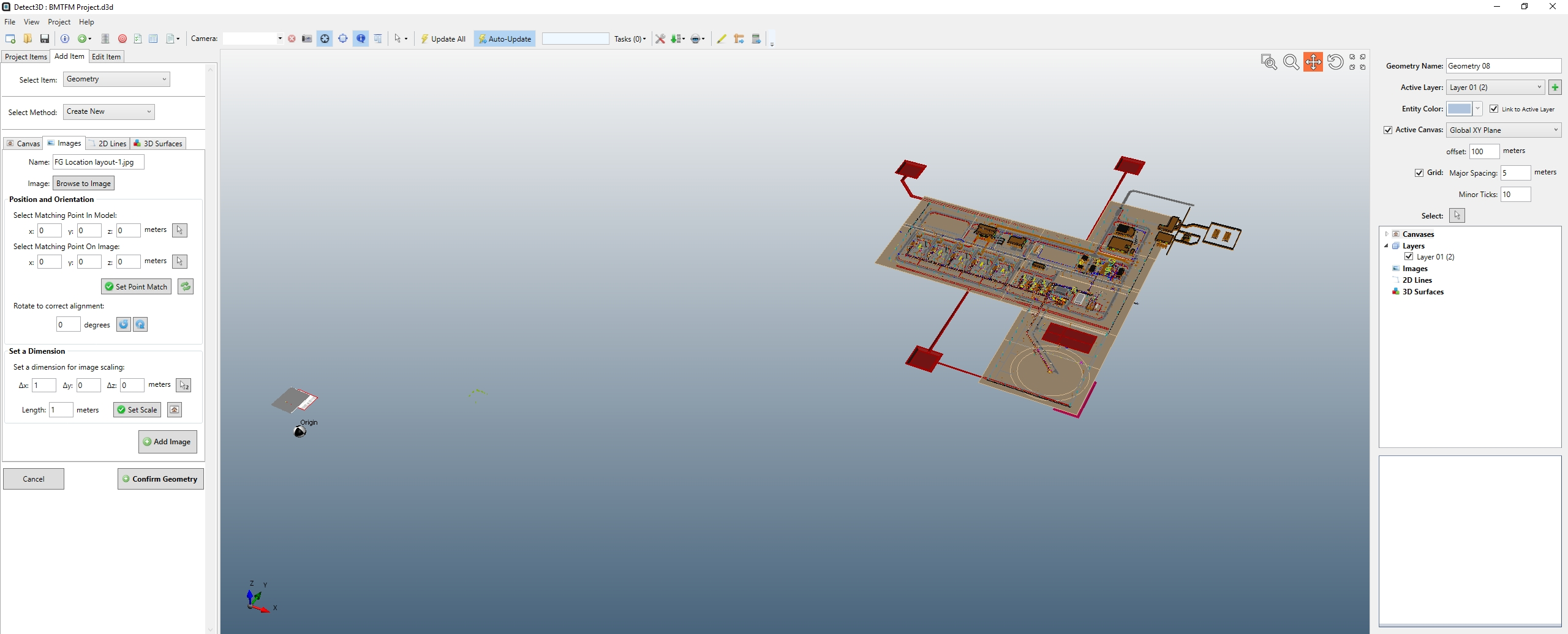
Zoomed in view of the imported file
7. You can see the canvas and grid overlays on the image – turn these off to make things clearer – uncheck the “Active Canvas” and “Grid” checkboxes on the top right.
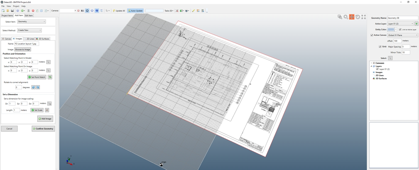
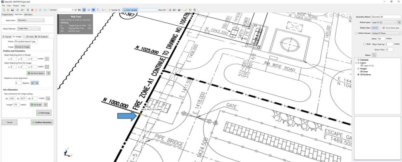
8. Now we are going to scale the image to the correct size. The trick is to find a good dimension on the image and use that to scale it. Fortunately, this drawing has the coordinates which exactly match the CAD file. We can use the North coordinates to scale the image. To do this, click the “Pick Tool” in the “Set a Dimension” group box on the Images tab. You will notice that the Pick Tool has a “2” on it – this means that it expects you to pick two points, i.e. the two ends of the dimension we’re going to use for scaling:
TIP! Press “g” while the Pick Tool is active – this deactivates the “Snap To Grid” and allows you to pick the points more accurately.
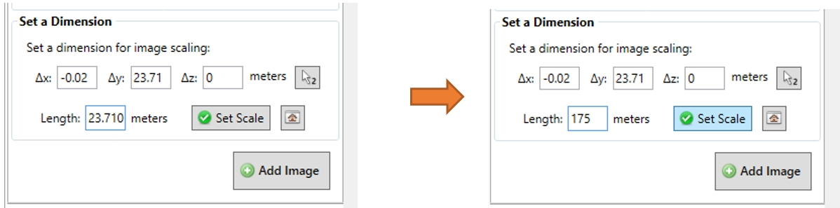
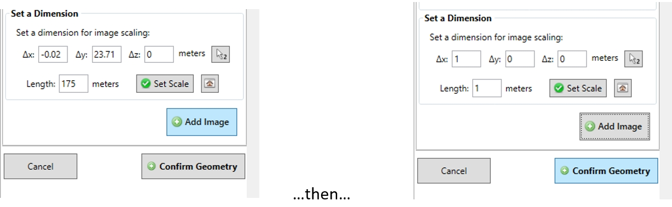
9. For this example, the size of the image is such that the selection above is 23.71 meters, but we know that the actual length is 1150 meters – 975 meters = 175 meters. So, overwrite the length to 175 meters and press “Set Scale”.
10. Zoom out to see that the image is now the right size! It’s still in the wrong place, so that need to be fixed. To do this, turn your attention to the “Position and Orientation” group box above the “Set Scale”. You will see two coordinate input boxes. The first asks you for a location on your CAD model, and the second asks you for the matching location on the image. For this example, the Pick Tool was used to pick out the N1000.00 E1400.00 point on the image:
11. With this point selected, type in these coordinates on the CAD file (x axis is East, y axis is North).
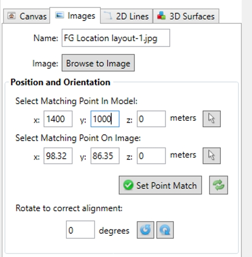
12. Once the points are typed in, click “Set Point Match” and the image will exactly align with the CAD file:
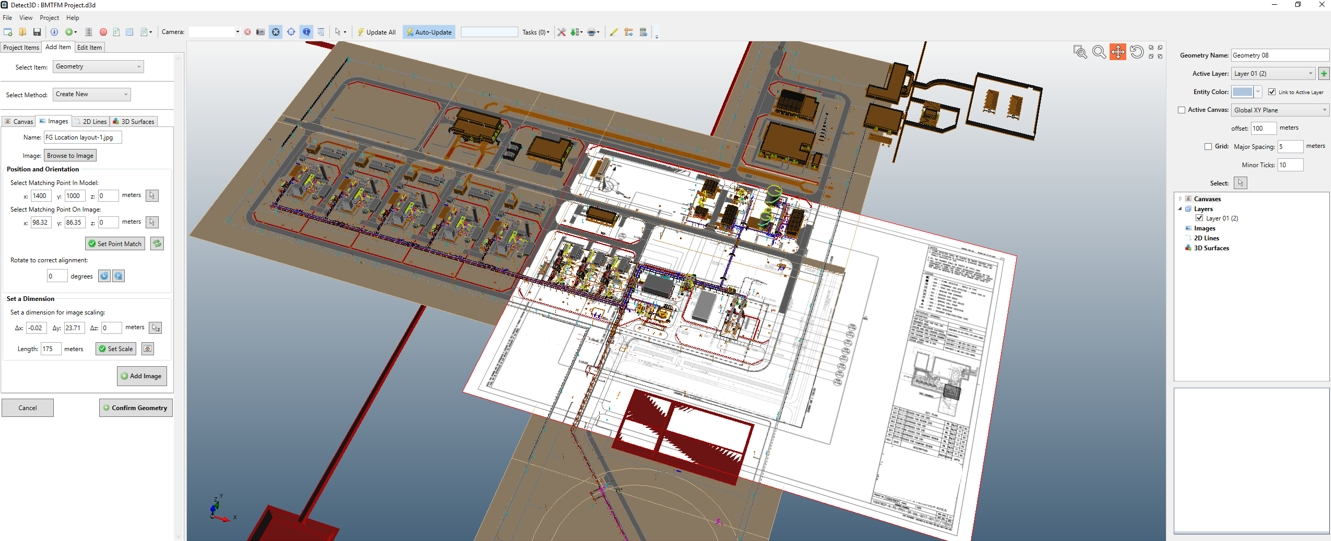
13. You can make slight adjustments to the z-coordinate of the point match to raise or lower the image to the desired height – sometimes when the image exactly lines on surfaces, the graphics card doesn’t know which to show and can lead to undesirable results.
You can choose either to raise the image or lower it and make the ground levels transparent. To lower it, edit the “Matching Point in Model” to -0.5 meters (for example). The image should now be “below” the CAD:
14. Click “Add Image” to add the image to the geometry you have created, then click “Confirm Geometry” to add the created geometry to the project. Don’t worry about the warning message, just click “OK”. You will notice that there is a new geometry listed in the project tree.
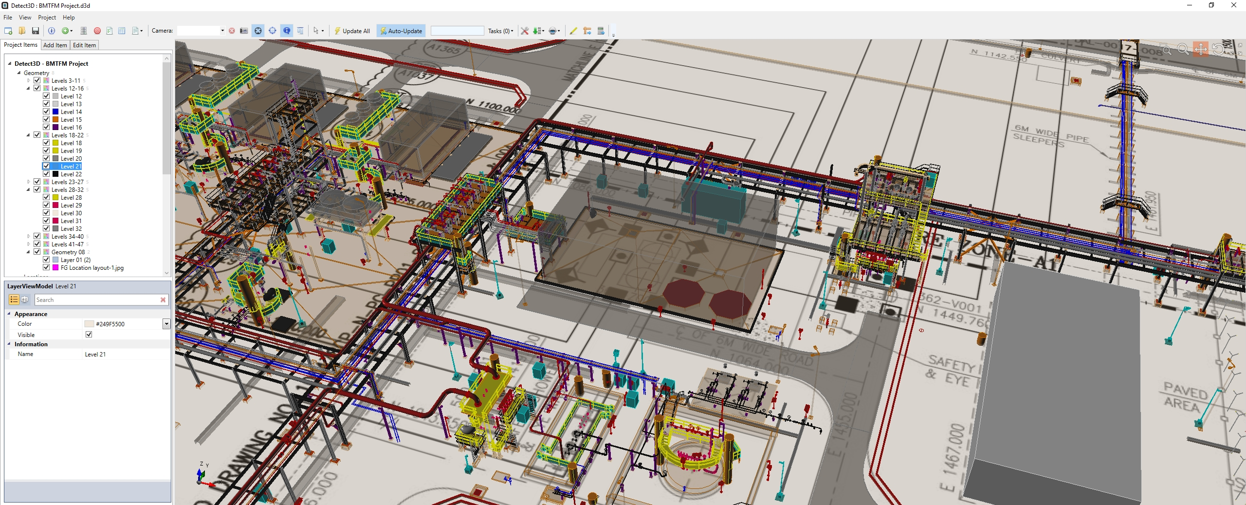
15. You can then play with the geometry and transparencies via the 'alpha' channel of the layer property to get the desired effect. If the image being lower than grade doesn’t work, you can always add the image again above grade etc. In the image below, the transparency was changed for one of the layers of the CAD
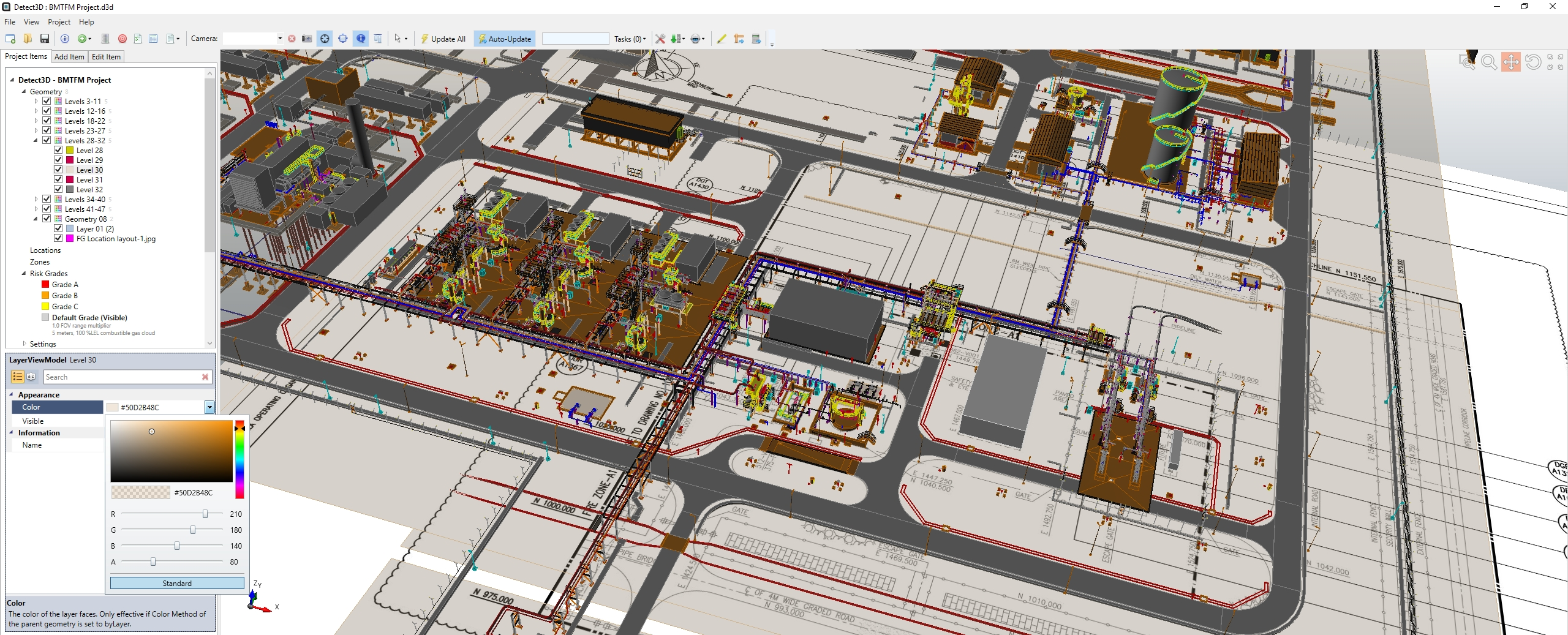
This can be done with more layers until you are pleased with the result.