Quick Cylinder
One of the ten options for 3D Surfaces in the CAD Creation Tool is the Cylinder.
A red button in the middle of the panel, , may be used to create a cylinder with just 3 clicks of a pick tool. The below images
describe the process of using the Quick Cylinder feature.
, may be used to create a cylinder with just 3 clicks of a pick tool. The below images
describe the process of using the Quick Cylinder feature.
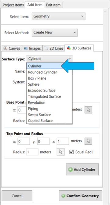
From the 3D Surfaces tab, select 'Cylinder' from the Surface Type dropdown menu
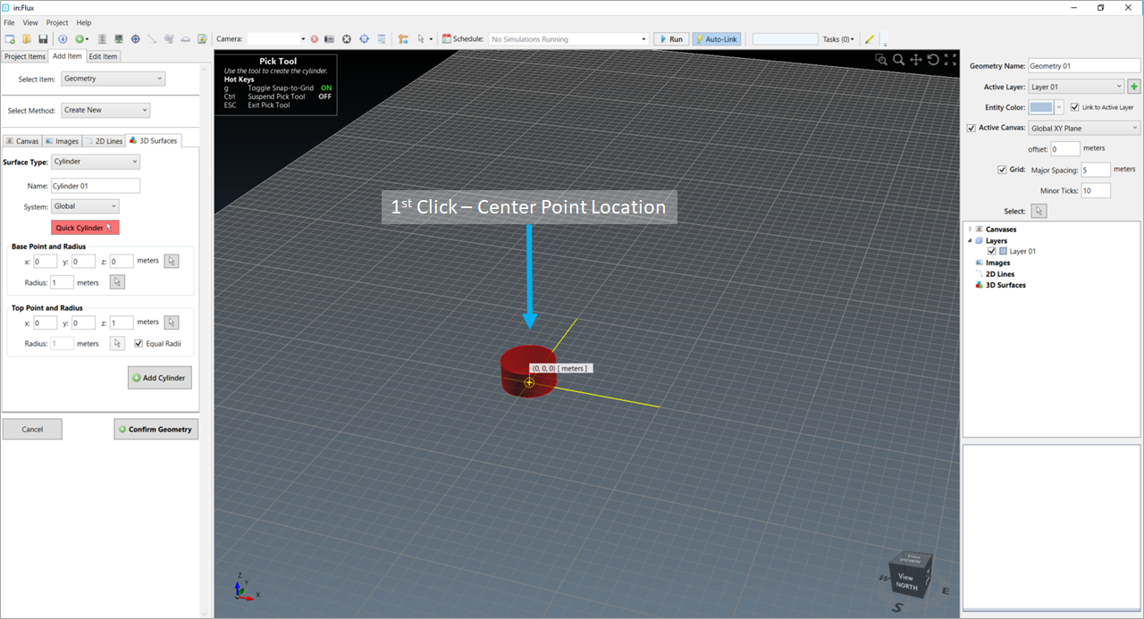
After selecting the red 'Quick Cylinder' button, a pick tool will appear. The first point selected on the canvas will be used as the center of the cylinder
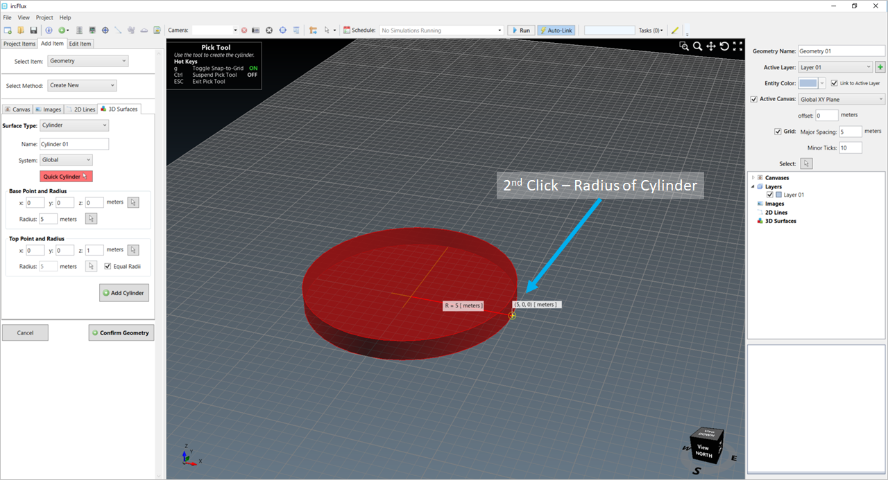
After the first point has been selected, the center will be recorded, and the transparent red cylinder will follow the mouse pointer expanding to its location. The 2nd selected point will correspond to the radius of the cylinder.
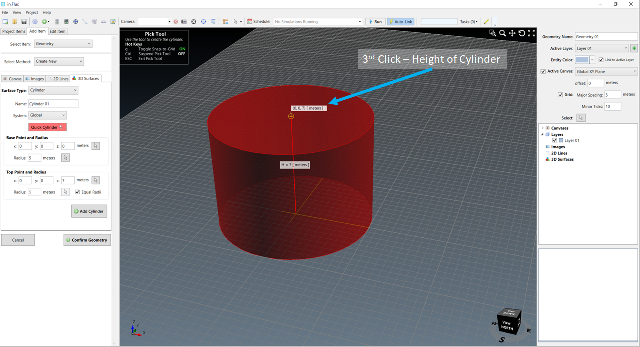
With the base created from the 1st two points (center and radius, respectively), the height can then be defined. The transparent red cylinder will follow the mouse pointer until a point is selected.
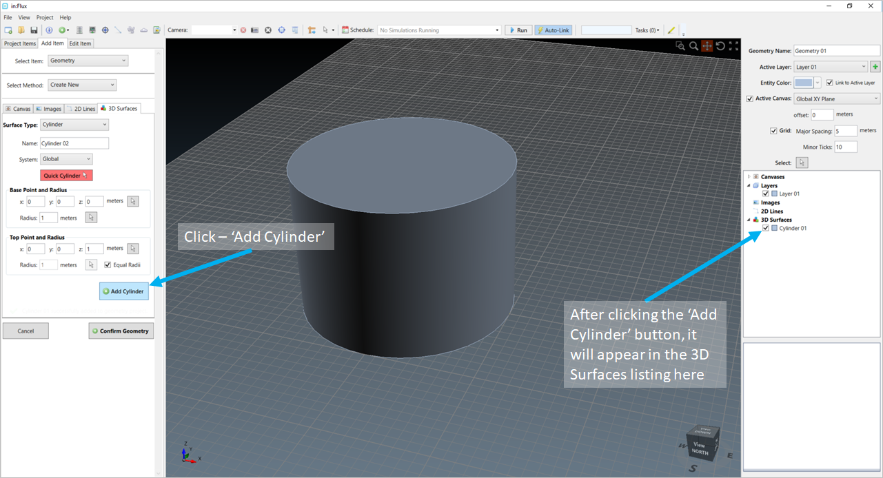
After the third point is selected, press the 'Add Cylinder' button to add the 3D Surface to the CAD Creation Project. It will be listed on the right-hand panel as indicated above.
Note that any CAD created in the above interface will not be properly accounted for unless the  button is clicked. Upon selection,
the normal Detect3D or in:Flux interface will appear, and the CAD can be used for future CFD analyses. Any simulations already completed will need to be recalculated to properly include the created CAD geometry.
button is clicked. Upon selection,
the normal Detect3D or in:Flux interface will appear, and the CAD can be used for future CFD analyses. Any simulations already completed will need to be recalculated to properly include the created CAD geometry.