Creating an Extruded Surface
Adding the polylines is the most complex part of creating geometries, but after a couple uses it will become a quick way to define simple or complex shapes to use in your created geometry.
We will extrude each of the polylines in this section to create the three-dimensional walls of the hangar.
Click the topic below to expand the section:
Extruded Surface 01Extruded Surface 01
For the extrusion of the first Polyline:
- Switch to the 3D Surfaces tab.
- Select Extruded Surface from the Surface Type dropdown menu.
- Leave the name set to Extruded Surface 01 and Canvas as the System.
- Polyline 01 has already been selected from the Lines list. You can maneuver the Viewport Window and see that Polyline 01 automatically starts out with a 1m extrusion as shown in Image 13 below. This gives you indication for which line you are working
with.
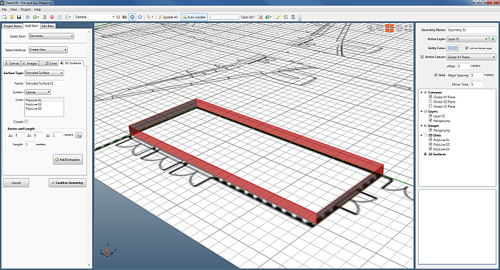
Image 13 - Automatic selection of Polyline 01 to make Extruded Surface 01 defaulted to 1m
- Select the Closed checkbox under the list of lines. This will make the extruded walls a solid, rather than an outline as in Image 9 above.
- In some cases, you may wish to change the vector or angle at which the polyline is being extruded. This can be done by changing the values under the Vector section. For this tutorial we will leave the values to (0, 0, 1) for delta-x, delta-y, and delta-z, respectively.
- To increase the height of the wall - enter a value of 6 meters into the Length text box.
- Click Add Extrusion. The box will turn a light-blue color to indicate it has been added to the geometry project, your viewport window should appear as Image 14 below.
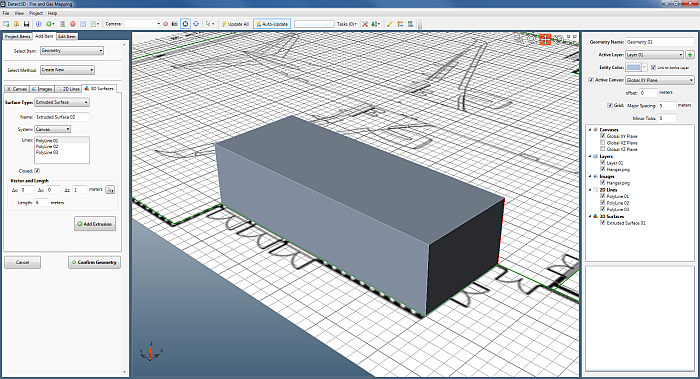
Image 14 - Displaying Extruded Surface 01 which was created by extruding Polyline 01 by 8 meters.
We will repeat these steps for extrusions for 2 more polylines.
Extruded Surface 02Extruded Surface 02
For the extrusion of the Polyline 02:
- Remaining in the 3D Surfaces tab, select Polyline 02 from the Lines list.
- Uncheck the Closed check box, as we will demonstrate other ways of closing extrude surfaces in later sections.
- Since we already entered a value of 6 meters for the first polyline, the value is kept for simplicity of extruding multiple polyline. The Viewport Window at this point should resemble Image 15 below.
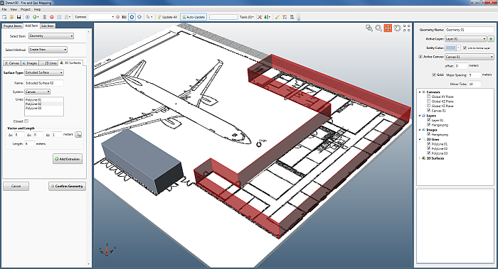
Image 15 - Upon selection of Polyline 02, the extrusion already is set to 8m
- Click Add Extrusion. The walls will turn a light-blue color to indicate that Extruded Surface 02 has been added to the geometry project.
Process to the next steps to extrude Polyline 03.
Extruded Surface 03Extruded Surface 03
For the extrusion of the Polyline 03:
- Remaining in the 3D Surfaces tab, select Polyline 03 from the Lines list.
- Enter a value of 15 meters as the length of the third Extruded Surface. The Viewport Window at this point should resemble Image 16 below.
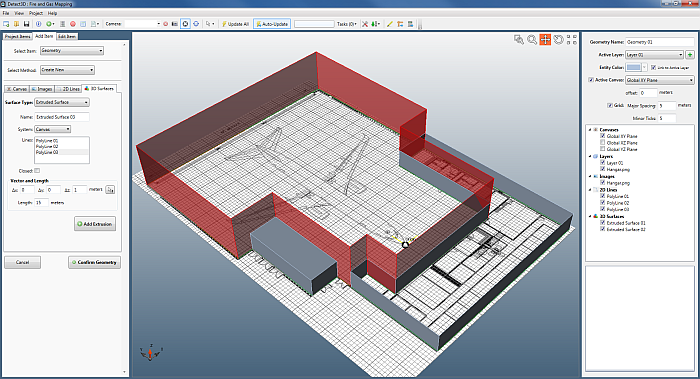
Image 16 - Upon selection of Polyline 04, the extrusion already is set to 16m
- Click Add Extrusion. The walls will turn a light-blue color to indicate that Extruded Surface 03 has been added to the geometry project.
Now that all the necessary polylines have been extruded, we will triangulate two of the polylines in the next section.