Tessellation Comparison
This section will go over a comparison of the various triangle reduction chord errors to provide a better understanding of the tessellation involved and the importance of reducing the triangle count to reduce the load on the computer's graphics and memory cards.
-
Open up a new project in Detect3D or in:Flux.
-
Locate the Refinery.stl file from the installation directory or from the Help Menu.
-
Load in the Refinery.stl file and wait for the CAD Import Options Window to appear as below
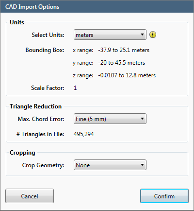
CAD Import Options Window for the Refinery.stl CAD file
-
The units and should be set to meters as the bounding box dimensions are appropriate for this project.
-
The Max. Chord Error has already been set to Fine (5mm) since there exists less than 500,000 triangles. Choose None from the Max. Chord Error dropdown menu.
-
We will not be using the Cropping Capability in this section. Leave the Crop Geometry: set to None.
-
Click Confirm to load the Refinery.stl file.
We will be loading the file 3 more times to compare the triangle reductions.
-
Load the Refinery.stl file a second time.
-
Choose meters from the Select Units Dropdown Menu
-
Set the Max. Chord Error value to Fine (5 mm).
-
Click Confirm.
-
Load one last Refinery.stl file and choose Medium (10mm) as the Max Chord Error.
-
Click Confirm to load the last geometry file for Tutorial 5.
Notice the splash window that appears while the triangle reduction is running (see below image). The percent compression is displayed on the left while the new number of triangles is displayed on the right. Note that many CAD files have 1000s of superfluous triangles representing mm level differences (sometimes smaller) so there is no need to worry that 80% or higher has been compressed as it will soon be described that a high level of accuracy is still maintained in the CAD.
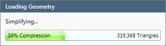
Loading Geometry window while triangle reduction is calculating.
You should now have 3 Refinery.stl files loaded
-
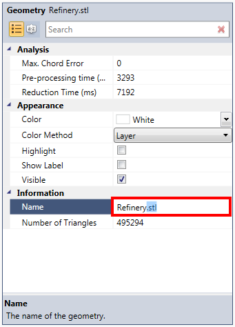
Change the name of the first geometry loaded to Refinery - Original by selecting it from the Project Items Tree and editing the Name text field under the Information header, shown below.
-
Change the name of the second geometry to Refinery - 5mm.
-
Change the name of the third geometry to Refinery - 10mm.
-
Turn off the visibility of the Refinery - 10mm and Refinery - 20mm by deselecting the checkboxes next to the names in the Project Items Tree.
-
In order to see the triangles of the CAD geometries we need to change the rendering of the Viewport Window. To do this right click anywhere in the Viewport Window and under the Rendering section select the Shaded option (shown below). You may also select the Shaded option for rendering from the View Menu on the toolbar.
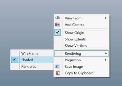
Selection of the Shaded rendering for the viewport window.
Once the rendering has been changed zoom into the boxed region shown:
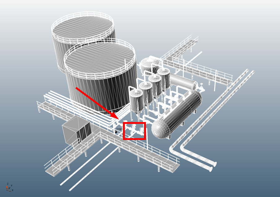
Region to zoom into on Refinery geometry.
The next three images below show how triangles are used to represent pipe work and valves in a geometry as well as the differences between a coarse tessellation (the 20mm triangle reduction) and a refined one (the original CAD file). You can view the same results as the screenshots below by zooming into the region indicated in Image 18 and toggling the visibility of each Refinery geometry.
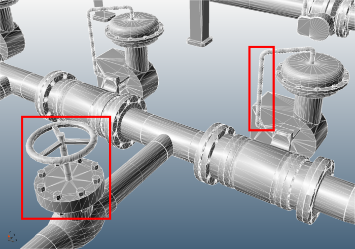
Refinery - Original (495,294 Triangles): The above image indicates two regions which are made up of several hundred triangles. Too many triangles have been used to represent these small regions which are almost insignificant for fire and gas mapping purposes. The following two images will show how even with less triangles you can still accurately represent pipes and values.

Refinery - 5mm (171,160 triangles): The number of triangles has been reduced to 35% of the original. The geometry is still well defined with several triangles make up the bolts and small pipes, a larger chord error would be better for this CAD file.
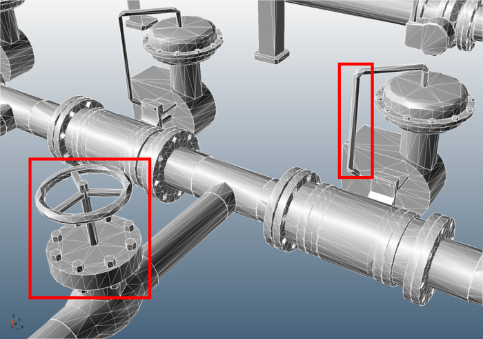
Refinery - 10mm (118,682 triangles): The 10mm triangle reduction is the recommended chord error for CAD files of more than 500,000 triangles. in:Flux reduced the triangles of the geometry to 24% of the original amount. Even though the triangles are coarse (could still be coarser) they still accurately represent the refinery geometry and will allow for much shorter analysis times.
NOTE: to reduce the load on the graphics card, users have the option to limit the size of the small triangles displayed by the graphics card. To change this setting:
-
Select Application Options from the Project Items Tree
-
Change the value of the Small Triangles Size to 10 (the default is set to 2).
-
Selecting Show Wireframe On Motion also assists in reducing the load on the graphics card.