Geometries with Large or UTM Coordinates
Some 3D CAD models are exported using different coordinate systems. If your file has geometry placed with the x and y coordinates being greater than 1,000,000, then it might be in the Universal Transverse Mercator (UTM) coordinate system or even latitude and longitude. In either case, having the model far away from the origin causes inaccuracies in the import process and display of the model in Detect3D or in:Flux.
How do I know if my file is in UTM Coorindates?
Below are two ways to check if you geometry has large coordinates or is in UTM:
-
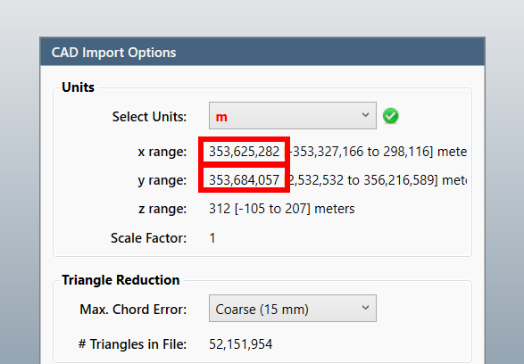
Looking at the CAD Import Options window, the stated X and Y ranges may be quite large as shown below
-
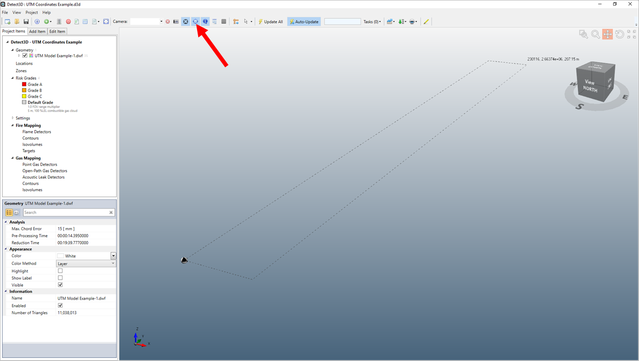
After importing the model, the 3D window appears blank (as if nothing was imported), but there is the model name located under the Geometry header in the Project Items Tab. You can verify that there is a model imported in the 3D window by click the bounding box icon on the toolbar. Example shown below. Here the 3D window has to zoom out so far that the 3D model is near impossible to see.
How do I Import Geometry if it is in UTM Coordinates?
If the above is applicable to your model, follow the below steps to import it:
-
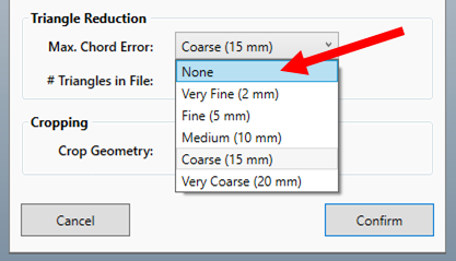
Import the CAD file but choose None for the option of the Max. Chord Error. It is useful to note down the suggested chord error before selecting the None option as we will use it later, in this case it was Coarse (15mm).
-
The software will import the geometry. It will still not display correctly – we have to translate the geometry back to some coordinates that are smaller.
-
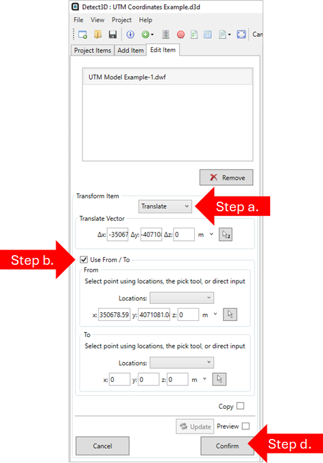
Go to Edit Item, select the geometry, then choose Translate
-
Select Use From / To checkbox and in the From box enter or use the pick tool to select a point that looks like a useful future Origin Point (perhaps a corner piece of a ground item). The form should look similar to the below. Note that the z-value in the From box should state “0” as probably the height is not the issue and shouldn’t be changed.
-
IMPORTANT – record and save the delta vector displayed in the Translate Vector field, in the below this is ⟨-350678.59, -4071081.08⟩. This vector will need to be added back to detector coordinates when reporting.
-
Click Confirm. After some processing, the geometry will be translated by the entered delta vector.
-
-
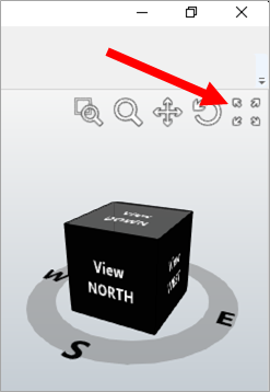
Click the “Zoom Fit” button in the upper-right corner of the 3D window to position the window around the newly positioned geometry.
-
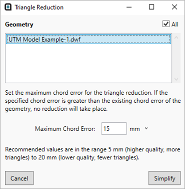
Finally, we need to simplify the geometry - select Simplify Geometry from the Project menu, then use the Chord Error suggested in Step 1 to reduce the triangle count.
To convert back to UTM coordinates in the future, such as after exporting detector coordinates, apply the translation vector that was used in Step 2c.