Adding a Contour
Contours are a quick and easy way to view detector coverage regions on a planar surface. Detect3D can add multiple contours on any of the three Cartesian planes: XY, YZ, or ZX. It is important to note that coverage calculations are still based on the volume of the zone and contours only provide a 2D visualization of coverage on the defined plane.
To add a contour to your project:
-
Click the Add Item tab and select Contour from the dropdown menu.
-
The Name of the contour is automatically set. Currently the name will read "z=0 meters Contour (Main Fire Zone)". As you edit the fields in the panel the name will automatically change. You may manually enter a name by unchecking the checkbox next to Auto. For the Detect3D tutorials the automatic name will be used.
-
Select Fire Zone: Main Fire Zone from the Zone dropdown menu if it has not already been selected.
-
Select XY as the On Plane option, putting the contour on a horizontal plane.
-
Set the Offset at: to Z = "3.5 meters". This will define the height of the contour plane.
-
Set the System to Zone. This means that the offset value in Step 5 will be based on the lowest z-coordinate of the zone. Otherwise, for the Global option, the origin (z=0) will be used.
-
Leave the Coverage as 0 to 4. This will set the contour to display the regions covered by 0, 1, 2, 3 and 4 detectors. You may opt to change the upper bought to be 3, as there are three detectors in the project, but it is suggested to leave these values as the defaulted ones. This can be changed after the contour is added to the project.
-
Click the Preview check box to view the contour.
-
The contour has initially been placed at a high level with little obstructions to make it easier to discern the overlapping fields-of-view and the colors associated with coverage areas. A description of each color is given below. Continue in Step 10 by lowering the height of the contour.

Tutorial 1 - Figure 21 - Preview of contour at 3.5m height in zone
-
Now change the Offset at: text box to "1.5 meters". The preview will update automatically. At this height more obstructions exist, and relevant information can be discerned of the position of the flame detectors and the resulting blind spots.
-
Click the Add Item button to add the contour to the project
The resulting 3D window should look similar to the figure below.
The Coverage Key will appear when the contour visibility is toggle on. The colors can be changed in the setting menu of the project items tree.
-
Black indicates areas seen by zero detectors.
-
Blue corresponds to areas seen by only one detector.
-
Red corresponds to areas seen by two detectors.
-
Green corresponds to areas seen by three detectors.
-
Yellow corresponds to areas seen by four detectors at the same time.
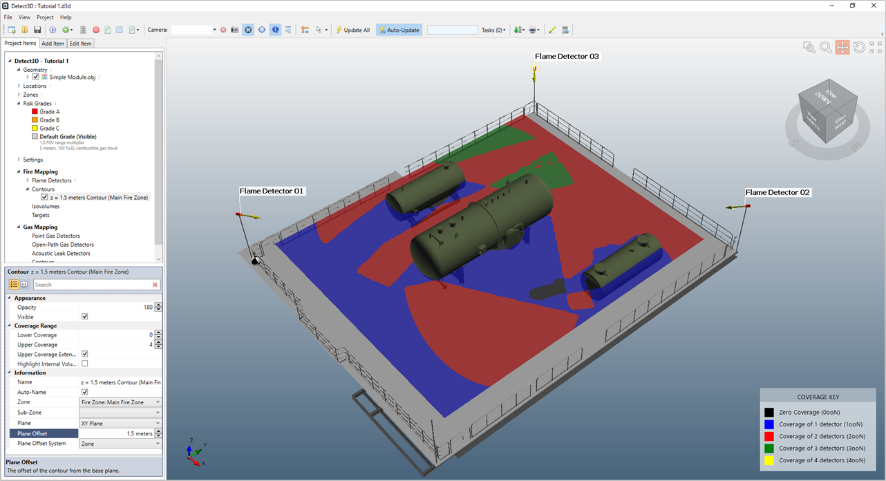
Tutorial 1 - Figure 22 - 3D Window with contour showing coverage of the three detectors on a plane at 1.5m height
Before continuing to the next section, turn off the visibility of the contour by deselecting the checkbox next to its name under the Fire Mapping-> Contours heading in the Project Items Tree.