Second Detector
Repeat the process for adding Flame Detector 01 by adding a second flame detector to the project:
-
From the Add Items Tab, select Flame Detector from the Select Items option
-
Enter the Name as “Flame Detector 02” if it is not already entered
-
Use the Point Pick Tool to select the point shown below as the Location of Flame Detector 02, or enter ( 18.05, 22.05, 3.59 ) into the coordinate text boxes
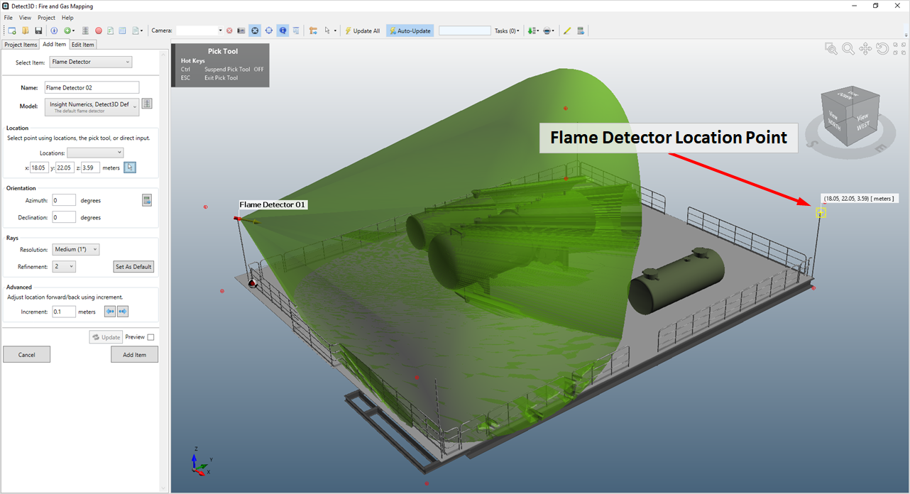
Tutorial 1 - Figure 09 - Flame Detector 02 location point indicated by the yellow crosshair of the Point Pick Tool
-
Click the preview button and see that the azimuth and declination values are kept from before. The azimuth then needs to be changed to the detector points towards the vessels. For Flame Detector 02, we will use the Flame Detector Aiming Tool. Click the target button (
 ) to activate the tool.
-
Once activated a special pick tool will appear with a line drawn from the coordinate entered in Step 3 to the mouse cursor.
-
Move the mouse cursor to the center of the vessel, similar to Figure 10 below.
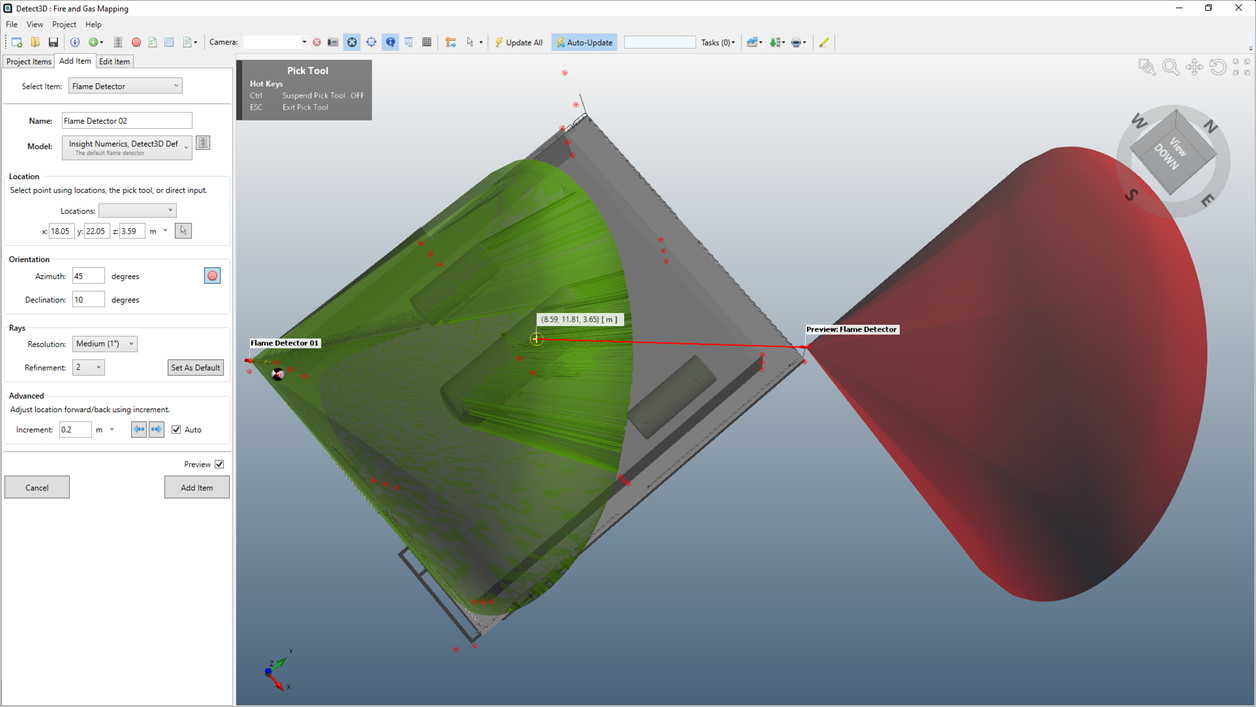
Tutorial 1 - Figure 10 - Flame Detector 02 preview before using Flame Detector Aiming Tool to update Azimuth Angle
-
Click the left mouse button once and the drawn ray will be used as the center line of the detector. The azimuth and declination values will be automatically calculated based on this vector and entered into the corresponding text boxes.
-
Using the above from a top view should give an Azimuth angle of about of "225 degrees". You may enter this value if you would like results to match the tutorial.
-
Looking from a top view however may not always give an appropriate declination angle, enter a Declination of "10 degrees" for this example.
-
-
You may see a warning sign, saying the The detector may be blocked by nearby geometry. To resolve this, click the Forward Arrow
 once to nudge the location of the detector by 0.2 m in the direction it is aimed
 -
Click Add Item Button to add the second flame detector to the project
The resulting 3D window should resemble Figure 11. Notice how initially the detector is displayed only with its model (small red cylinder) and direction (yellow arrow).
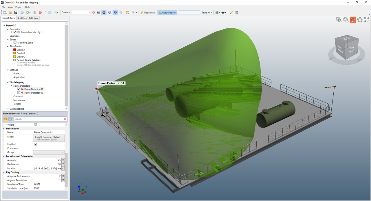
Tutorial 1 - Figure 11 - The unobstructed view for the first two flame detectors added to the project.
You can change the visibility properties of all the detectors at the same time or individually. Right-click on the Flame Detectors header item shown in Figure 12 and select Toggle All Labels. Do this a second time and choose Toggle All Obstructed FOVs. This will turn on both detector FOVs which is quite cluttered for just two detectors, repeat this process of choosing Toggle All Obstructed FOVs again to turn off their visibility.
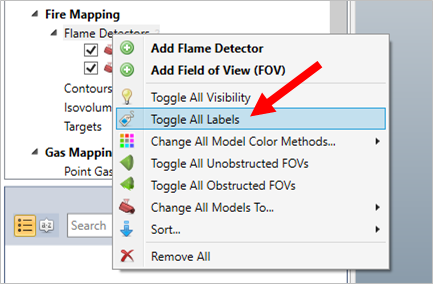
Tutorial 1 - Figure 12 - Right-clicking the flame detectors header to toggle visibility items for all detectors in the project
Your window should appear similar to Figure 13 with both labels showing for each of the detectors in the project.
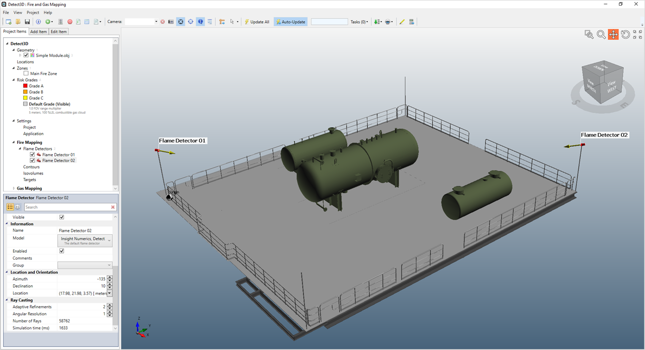
Tutorial 1 - Figure 13 - 3D window with two flame detectors added with their labels displayed