Importing a Geometry and Defining a Gas Zone
Add the Simple Module geometry to a new project:
-
Click the Add Item tab and select Geometry from the dropdown menu.
-
Select the Import button and navigate to Simple Module.obj in the Detect3D directory and click Open.
-
Ensure that meters is chosen as the Selected Units and None is set as the Max. Chord Error and click Confirm.
For this tutorial a gas zone will be used, but using the default setting, Type set to Fire and Gas Mapping, will generate the same results.
To add a Gas Zone to the project:
-
Right-click Zones in the Project Items Tab and select
 from the menu that appears. This is also the same as selecting the Add Item tab and choosing Zone from the dropdown menu
 -
Set the Name of the zone to “Main Gas Zone”
-
Select Gas Mapping Only as the Type and set the Risk Grade set to Default Grade
-
Enter the coordinates ( 1, 1, 0 ) into the x, y, and z fields for Point 1
-
For Point 2 of the gas zone, enter the coordinates ( 17, 21, 4.5 )
-
Leave the Type as Geographic: Point and the Resolution set to Medium (0.25 m).
-
Click the Preview check box to view the defined zone and verify that it resembles the image below.
-
Select the Add Item button to add Main Gas Zone to the project
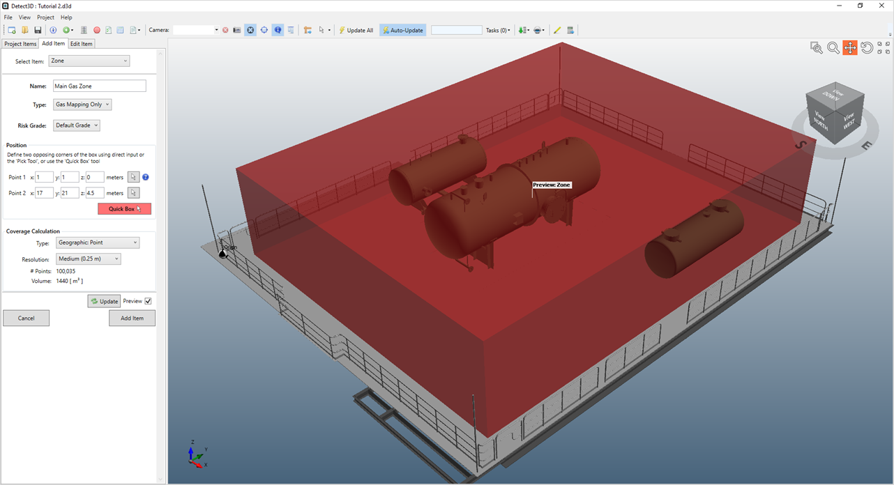
Tutorial 2 - Figure 01 - preview of Main Gas Zone in the Simple Module geometry
Adding the zone to the project will change its color to a transparent gray color. The named gas zone is now listed in the Project Items tab. Deselect the checkbox next to its name to turn off the visibility of the zone. Selecting and un-selecting checkboxes in this way only toggles the visibility of the item.