First Sub-Zone with Quick Box Tool
For the first sub-zone, the Quick Box tool will be used to define a cuboid sub-zone around one of the pieces of equipment in the geometry. The Quick Box is defined by three clicks as shown in Figure 05: 1st click is the starting coordinate, 2nd click is the width and length, and 3rd click is the height. After selecting the three defining points the associated coordinates will be entered in the Point 1 and Point 2 text boxes.
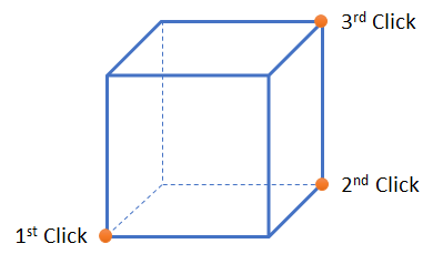
Tutorial 4 - Figure 05 - Diagram describing the three clicks used with the 'Quick Box' function in Detect3D
Before continuing, to facilitate adding sub-zones in and around the geometry with a deck, the structure layer will be visibly toggled off. To do this, expand the layers of the geometry file by clicking the small triangle next to the Complex Module.obj text, indicated by the red arrow in Figure 06 and deselect the checkbox next to the Structure layer. Your geometry should appear now without the dark gray structure layer, as is shown in Figure 07.
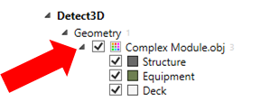
Tutorial 4 - Figure 06 - opening the layers of the imported geometry file to toggle one of the layers off
To add the first sub-zone:
-
Click the Add Item tab and select Sub-Zone from the dropdown menu
-
Leave the Name set as “Sub-Zone 01”
-
Ensure that the Zone is set to the Main Zone
-
Select Grade B as the Risk Grade
-
Leave the Type set to Standard Cuboid
-
In the Position section click the red, Quick Box arrow button (
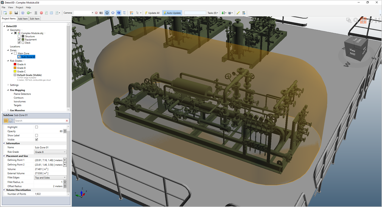
 ), the Pick Tool Hot Keys will appear in the upper left corner of the 3D window. Use the Quick Box tool and match the three clicks labeled in Figure 06 below. Alternatively, you may enter the following coordinates for Point 1 ( 23.51, 7.13, 1.48 ) and Point 2 ( 20.81, 1.43, 3.68 )
Tutorial 4 - Figure 07 - Using the 'Quick Box' option to define Sub-Zone 01
-
Click the Preview checkbox to see the preview of the cuboid sub-zone.
-
In the Filleting section change the Select Edges to Top and Sides. This will add a fillet to the edges of the defined box. The fillet radius sets the amount of curvature and can be set to make circular sub-zones if needed. For now leave the Radius as "1 meter" which will result in the 3D window appearing as Figure 08 below

Tutorial 4 - Figure 08 - Preview of Sub-Zone 01 with a 1 meter fillet radius applied
-
Click the Add Item button to add Sub-Zone 01 to the project
The resulting sub-zone should appear similar to Figure 09. If your zone is a different color, then the incorrect risk grade was assigned in Step 4 above. Return to Project Items tab and switch the Sub-Zone 01 risk grade option in its properties panel to Grade B.
Tutorial 4 - Figure 09 - Sub-Zone 01 added to the project items tab with a transparent orange color from being associated with Grade B
Each grade has a different color associated with it. The default coloring is: red for Grade A, orange for Grade B, yellow for Grade C and gray for the Default Grade. You can change the colors of each in the Risk Grade's properties panel.