Adding a Sub-Zone Contour
Contours and isovolumes can be added to sub-zone regions as well as main zone regions. This allows for easier viewing of results for congested regions where sub-zones are more applicable.
To add a contour for a sub-zone region:
-
Click the Add Item tab and select Contour from the dropdown menu.
-
Leave the Name of the contour as its automatically defined one
-
Select Fire Zone: Main Fire Zone as the Zone
-
Click the blue Add Sub-Zone text to the right of the Zone dropdown menu as shown in Figure 25.
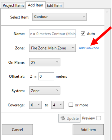
Tutorial 4 - Figure 25 - Selection of 'Add Sub-Zone' text to open the dropdown menu for selection of sub-zones for a contour
-
In the Sub-Zone dropdown menu that appears, select Sub-Zone 01
-
Ensure the On Plane option is set to the XY plane
-
Set the height of the plane to have an Offset at "0.75 meters"
-
Set the System as Zone. This sets the offset value to be from the base of the sub-zone rather than based on the global origin height of z=0
-
Leave the Coverage options as 0 to 4
-
Click the Preview checkbox to view the contour.
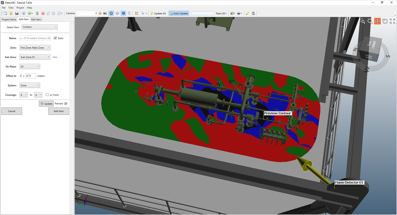
Tutorial 4 - Figure 26 - Preview of contour in Sub-Zone 01 at 0.75m height
-
Contours can be previewed in different zone or sub-zones before being added to the project. Continue by changing the Sub-Zone dropdown menu to select Sub-Zone 03
-
The preivew of the contour will automatically move to Sub-Zone 03 as in Figure 27 below
-
Select the Add Item button to add the sub-zone contour to the project. This will turn the contour slightly transparent, which can be changed in the Opacity section of its properties panel.
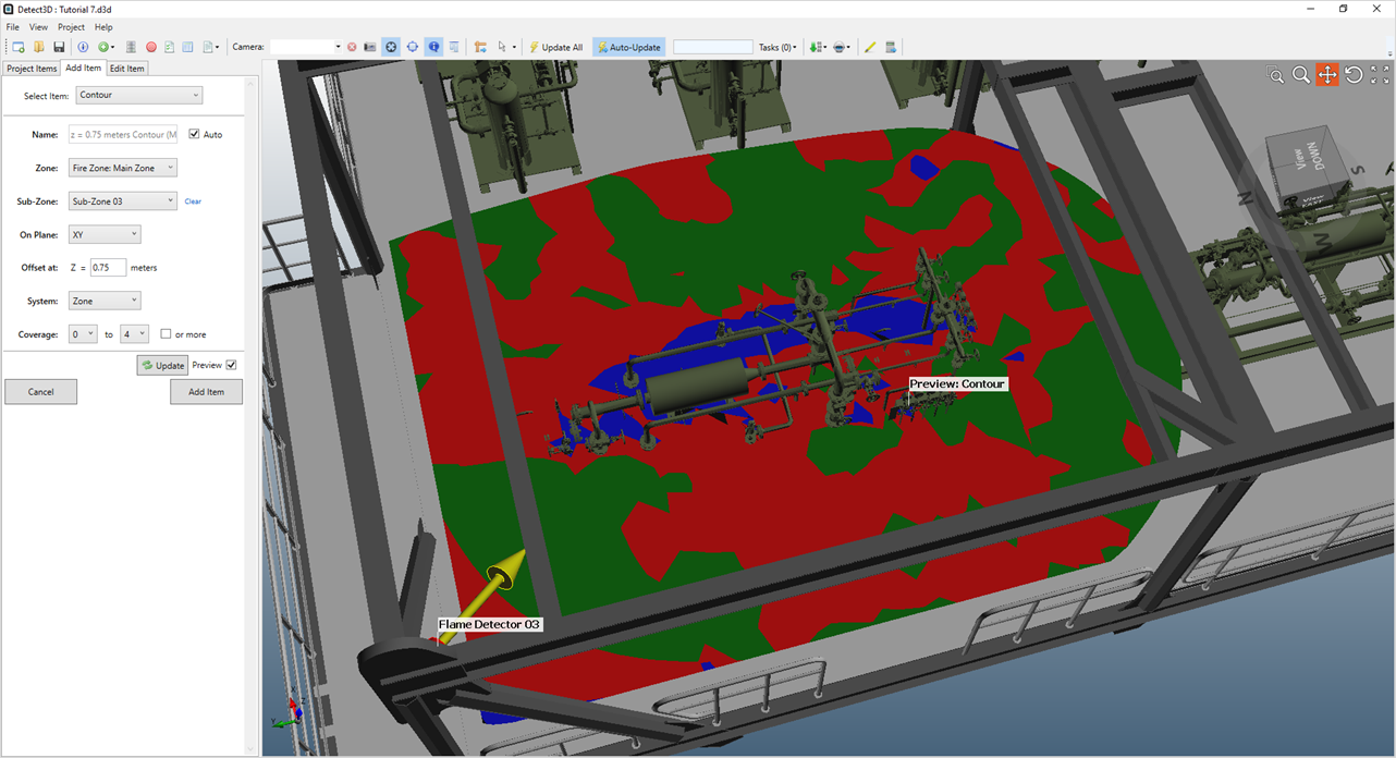
Tutorial 4 - Figure 27 - Horizontal contour added inside the bounds of Sub-Zone 03
Before continuing to the next section, turn off the visibility of the contour by deselecting the checkbox next to its name under the Fire Mapping-> Contours heading in the Project Items Tree.