Zone Definition
Define the fire zone for the project:
-
From the Project Items Tab, right-click Zones and select
 from the menu that appears. This will take you to the Add Items tab.
 -
Set the Name of the zone to “Main Zone”
-
Leave the Type as Fire and Gas Mapping
-
Set the Risk Grade as Default Grade
-
Use the Pick Tool
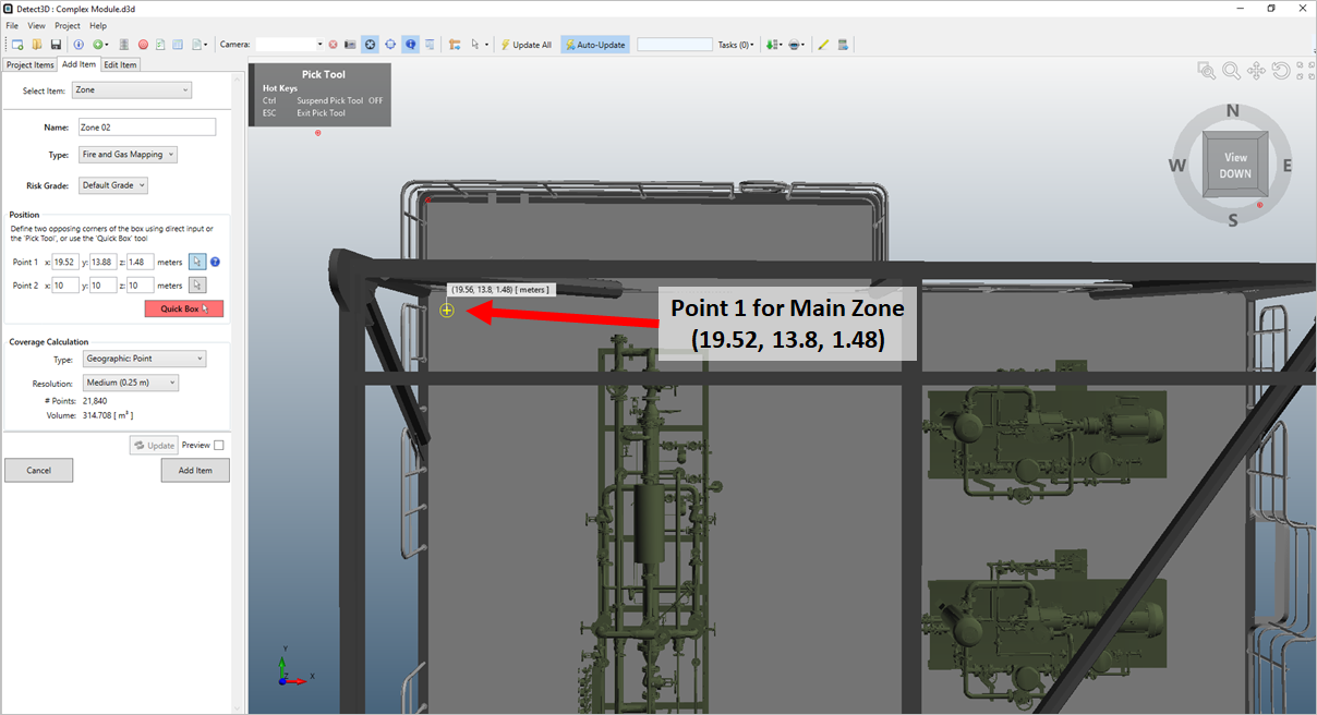
 for Point 1 and select a point at the north-west corner of the deck near the end of the row of compressors as indicated
in Figure 02 or enter the coordinates ( 19.52, 13.8, 1.48 ). Note that for this geometry, the deck is positioned at 1.48 meters and not at z=0.
Tutorial 4 - Figure 02 - Point 1 for the Main Zone.
-
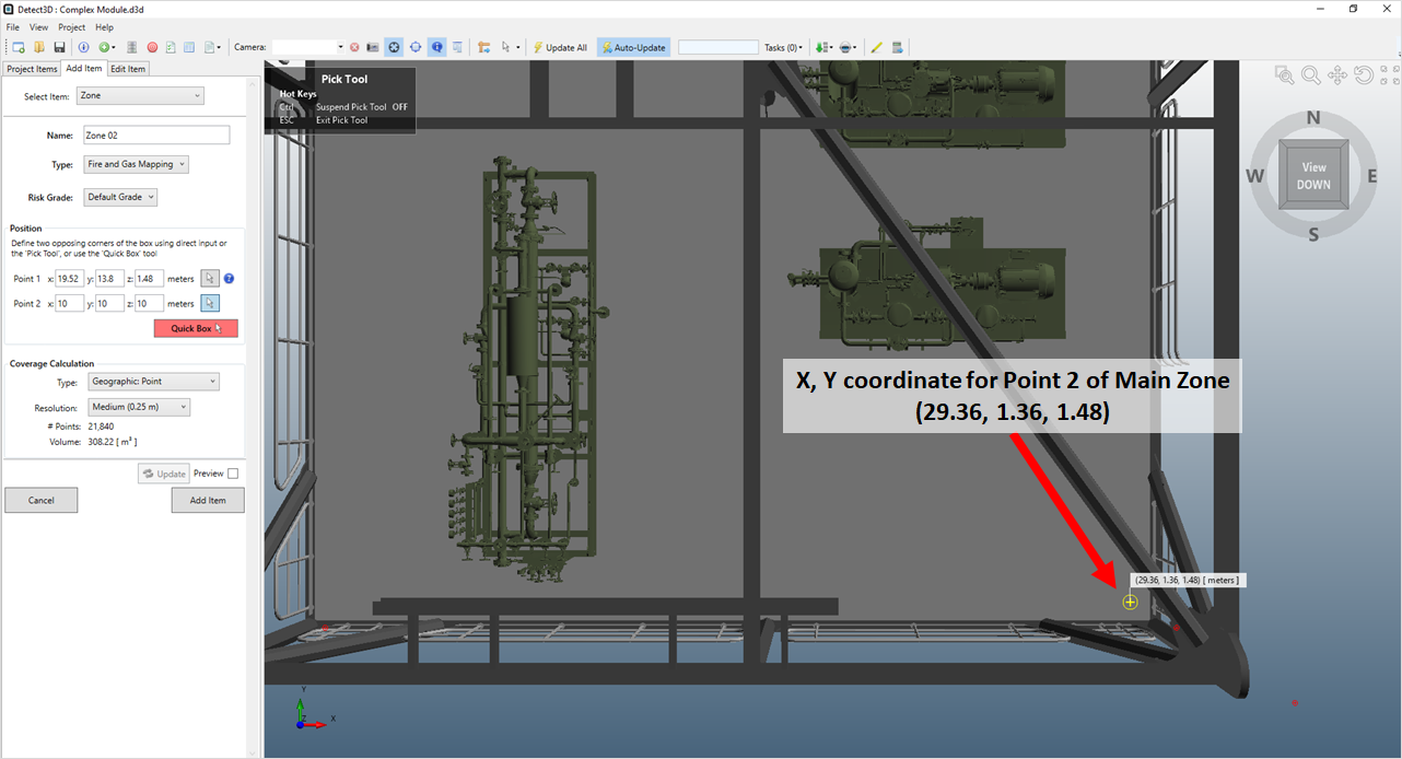
For the Point 2 use the Pick Tool a second time to select as point in the opposing south-east corner of the deck, as shown in Figure 03. Once the X and Y coordinates have been selected with the pick tool, enter a value of "5" as the z-coordinate. You may also manually enter the coordinates manually ( 29.36, 1.36, 5 ).

Tutorial 4 - Figure 03 - x and y coordinates being selected by the pick tool for Point 2, after selecting enter a z-value of 5 meters for the height
-
Set the Type as Geographic: Point and the Resolution to Medium (0.25 m)
-
Click the Add Item button to add Main Zone to the project
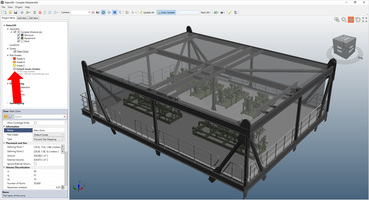
Switch to the Project Items tab and select the checkbox for Main Zone and ensure your 3D window is similar to Figure 04 below. Notice how the zone has a gray transparent color. This is because the Default Grade chosen in Step 4 above, has a gray color assigned to it. This is shown in the Project Items tab (indicated by the red arrow) and can be changed in the property panel for the risk grade.

Tutorial 4 - Figure 04 - Main Zone added to the Detect3D project with indication of Risk Grade coloring in the Project Items tab
The next sections will go over defining sub-zones in three different ways, each with a different risk grade assigned to it.
Deselect the checkbox next to the Main Zone to turn off its visibility before continuing.