Gas Detector Voting
All prior tutorials have only changed the low alarm value for the risk grade. In this section we will go over the use of the high alarm value and how the Control Voting Logic works in Detect3D, but this process is not typically a requirement for projects.
The Control Voting Logic will affect both point and open path gas detector 2ooN coverage calculations based on the high and low alarm distances entered in the Risk Grade properties panel. Contours and isovolumes can will also be affected by these alarm settings.
To add a high and low alarm distances to a risk grade:
-
Assign the Default risk grade to the Main Gas Zone, and make it the FOI Viewing Default.
-
Select the Default risk grade from the Project Item tab and in its properties panel, under the new Performance Requirements - Gas section, enter a Gas Cloud Size (High Alarm) size such as "7 meters"
-
Enter a Gas Cloud Size (Low Alarm) value of "12 meters". The low alarm distance is typically larger than the high alarm.
-
Leave the Control Voting Logic as LoLo for now. This is the default setting for all risk grades.
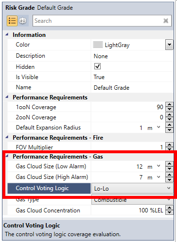
Tutorial 6 - Figure 10 - Updated Risk Grade properties panel with Low and High alarm gas cloud sizes
At the moment, the 3D window will display gas detectors based on the Low Alarm value of 12 meters, shown below. This is due to the Control Voting Logic set to LoLo, which is described next.
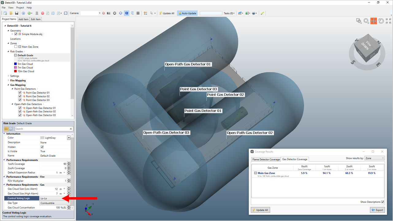
Tutorial 6 - Figure 11 - 3D window showing the low alarm setting of a 12m gas cloud
Based on the alarm distances entered, the calculated 2ooN coverage values will change based on the voting logic selected. The voting logic can be set to LoLo, LoHi, or HiHi as defined by the figures below.
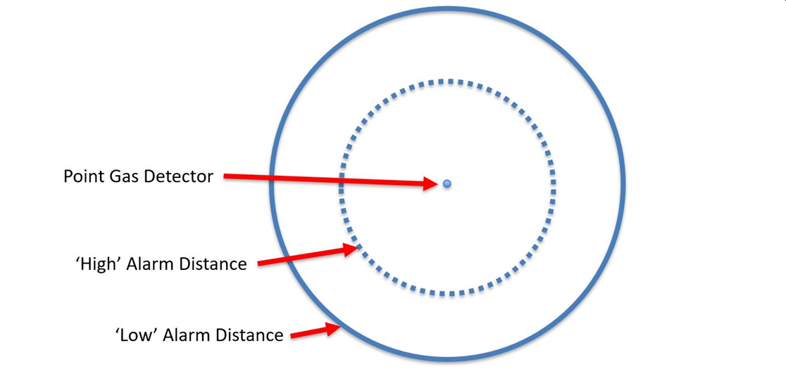
Tutorial 6 - Figure 12 - Diagram of a single point gas detector and its user defined low alarm (solid blue line) and high alarm (dotted blue line) distances
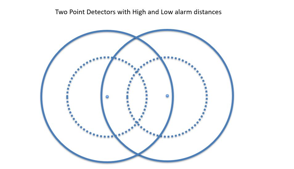
Tutorial 6 - Figure 13 -Diagram of two point gas detectors showing both of the defined alarm distances - low alarm (solid blue line) and high alarm (dotted blue line)

|
Tutorial 6 - Figure 14 For HiHi alarm settings, the shaded area for 2ooN coverage is the overlapping regions of high alarm distances (left). For LoHi alarm settings, the shaded area is the regions covered by one high alarm and one low alarm (center). For LoLo alarm settings, the shaded area for 2ooN coverage is the overlapping regions of low alarm distances (right). |
The 1ooN coverage values are always based on the entered low alarm distance. This is regardless of the Control Voting Logic. Meaning, if HiHi is selected for the control voting logic, the 1ooN gas cloud size will still be based only on the Low Alarm gas cloud size. If the LoLo or LoHi is selected the 1ooN gas cloud size will also be taken from the Low Alarm gas cloud size.
You can quickly compare the achieved coverages for the varying alarm levels by changing the Control Voting Logic option in the Risk Grade Properties Panel and clicking the Update All button on the toolbar or coverage results window.
In your project, switch between the three options for the Voting Logic based on the 12 meter low alarm and 7 meter high alarm defined above. A comparison of the coverages achieved for each voting logic is shown below.
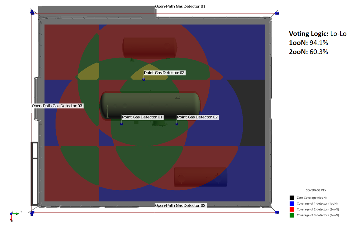
Tutorial 6 - Figure 15 - LoLo Voting Logic applied to the Default Risk grade for the project
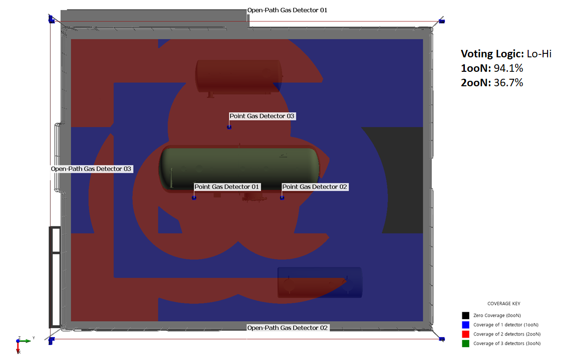
Tutorial 6 - Figure 16 - LoHi Voting Logic applied to the Default Risk grade for the project
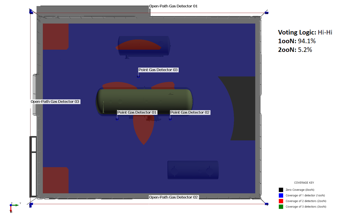
Tutorial 6 - Figure 17 - HiHi Voting Logic applied to the Default Risk grade for the project
This concludes Tutorial 6. You should now have an understanding of how to change gas cloud sizes in Detect3D, change the FOI Viewing Default as well as assign a Control Voting Logic to the project.
When you have finished viewing the results save and close the project.