FOV Blending
Occasionally, manufacturer spec sheets display a straight edge representing parts the edges or curvatures of the FOV. To take these edges into account, there is a blending option when creating a flame detector model in Detect3D
Three blending options exist for flame detector models in Detect3D: Bezier, Blend, Straight. For the model created in this tutorial use the Bezier Blending option.
Bezier
The Bezier blending makes use of the mathematical function known as a Bezier Curve to represent the smooth transition from the field-of-view edge towards the center line. This is the default option when creating a flame detector model.
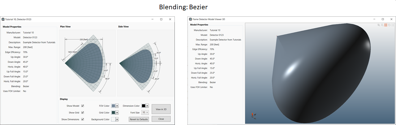
Tutorial 10 - Figure 10 - Preview of FOV model with a Bezier Curve
Straight
The Straight blending option removes the curvature between the edges of the field-of-view and the center line. Thus making the FOV appear more as a cone with sharper edges when compared to its bezier counterpart. Setting the blending the straight for the Tutorial 10 detector produces a FOV as shown in the image below.
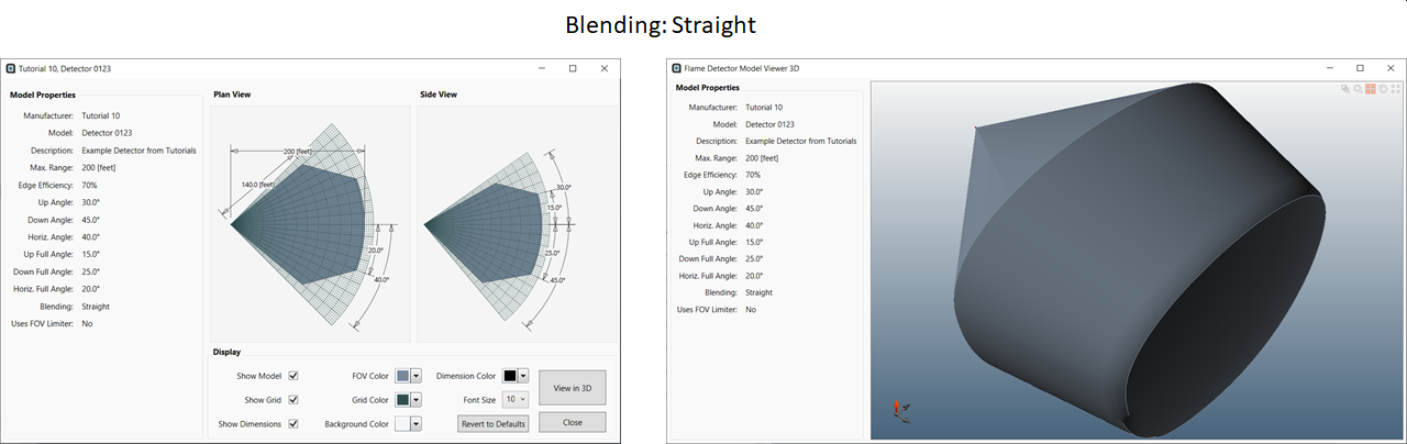
Tutorial 10 - Figure 11 - Preview of FOV model with Straight Edges
Blend
The Blend option for field-of-view blending provides an option for between the Bezier curve and the straight edge. The edges at the 'front' of the FOV are more rounded in the blend option than the straight. The image below shows the Tutorial 10 flame detector model with the blending set to Blend.
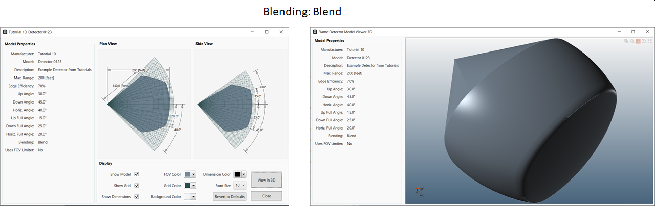
Tutorial 10 - Figure 12 - Preview of FOV model with a Blended Curve
Ensure that the Blending option is set to Bezier before continuing.