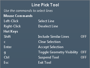
Line Pick Tool
The Line Pick Tool can be used on lines created in the Create Geometry Tool, or lines of an imported 2D DWG file.
Once opened the below window will appear in the top left of the Viewport Window. The commands are similar to that of the other pick tools, with the exception of pressing the Shift key while choosing a line will select not only the chosen line but the other similar lines. Meaning that in the DWG file, all the lines in the same layer will be selected.
The pick tool can be accessed in the Create Geometry Tool under the "3D Surfaces" Tab. Three surface types make use of the Line Pick Tool:
-
Extrude Surface
-
Revolution
-
Piping
The following explanations will make use of a 2D DWG file to describe the tool.
Extrude Surface
The Line Pick Tool can be used to extrude lines from 2D DWG AutoCAD files as well as other lines already defined in the Create Geometry Tool. Using the left mouse button simply click lines which you would like to extrude. The right mouse button can be used to deselect lines which have already been selected. The Viewport Window will automatically show the intended extrusion of the line.
The parameters on the left panel will define the vector the line is extruded along as well as the length of the vector. You may also choose to select the Closed checkbox to make the extruded line a solid rather than a 'walled' region.
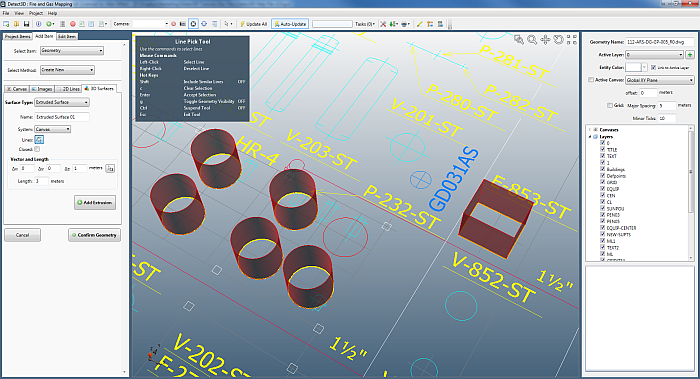
Image of the Line Pick Tool being used to extrude five circles and two lines.
Clicking the 'Add Extrusion' button will add the extruded lines to the Create Geometry Project. You can then define layers for organizational and coloring purposes.
Revolution
The Line Pick Tool can be used to create a 3D surface by revolving a single line (or a set of lines) around another. The images below show that first a revolution axis should be selected, this line will be the point of revolution for the other selected lines. The lines to be revolved are then chosen. On the left panel values are then entered for the angles to revolve around, in the below the values of 0 and 360 are used. Lastly, a translation vector can be entered to move the revolved surface from its pre-defined location (i.e. translate the surface up 1 meter so that it is not at ground level, as in the example below).
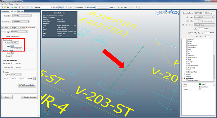
Choosing the revolution axis for a tank on the imported 2D DWG file.
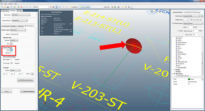
Once the rotational axis was selected, the lines to be rotate can be selected using the Line Pick Tool. The image above shows the line at the end of the tank being selected.
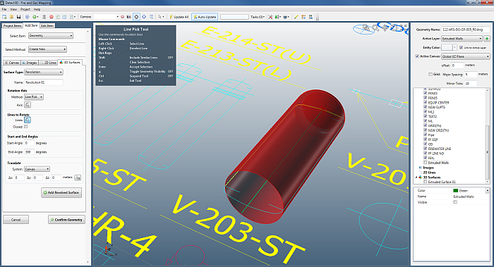
More lines are added to the revolution.
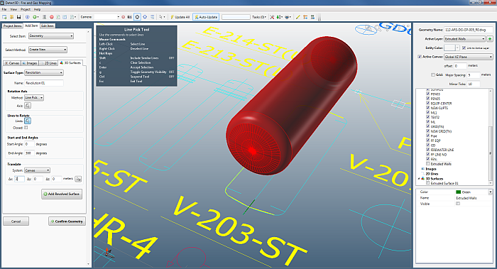
The lines defining the foreground end-cap of the tank are chosen to close off the tank. It is then translated up to be off ground level.
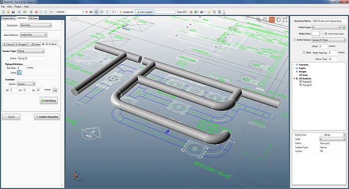
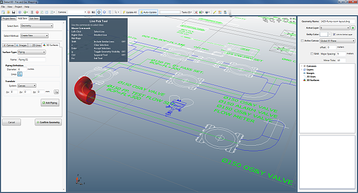
Piping
The third option for using the Line Pick Tool is the piping capability which is an option in the 3D surfaces section of the CAD Geometry Tool. After entering the diameter of the pipe to be drawn, select the center line of the pipe (indicated by the red arrows in the image below).
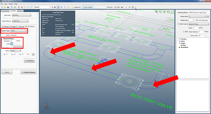
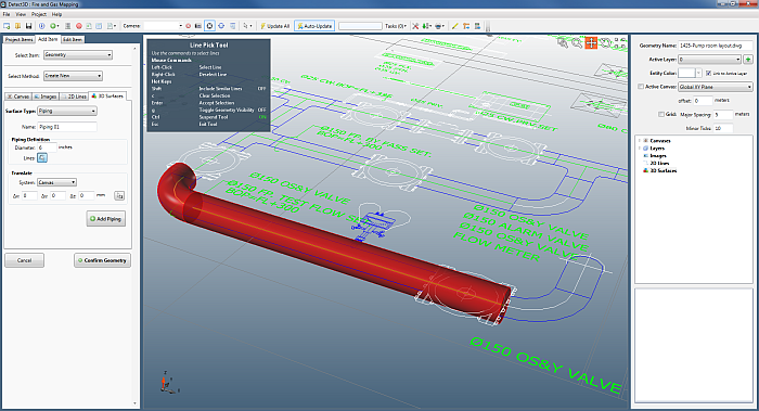
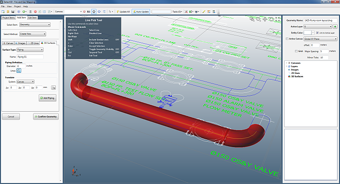
Each click with the left mouse button will draw a preview (in red) of the entered diameter pipe around the clicked center line. The Line Pick Tool for piping will work for curved lines as well as straight lines. The image below shows a single curved line having been selected by the Line Pick Tool. The following two images show two more lines picked to draw piping. If a wrong line is chosen, undo the selection by right-clicking the desired line to be removed from the previewed piping.
Once finished selecting the desired lines, you may translate the 3D surface by any entered vector. The image below shows the piping translated up along the z-axis.
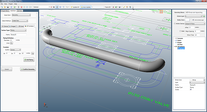
This process can be repeated for any number of lines, making creating pipe racks and other complex 3D surfaces easy to create in just a few clicks.