Picking CAD Geometry for Simulations
Users can select which geometry you want to include in your simulations. This is especially useful when you want to compare results with and without particular geometry pieces.
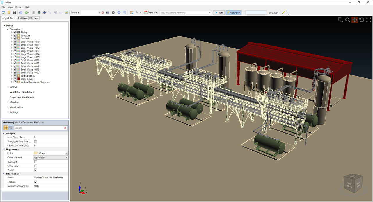
The below example will look at the following project file with 17 included geometries to represent the facility:
By default, all geometry is included, but to specifically select the geometry you want to include in a ventilation simulation:
-
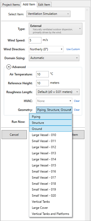
Expand the Advanced options section when defining a ventilation simulation
-
Select the geometry you want included in the simulation from the Geometry dropdown menu. The dispersion simulation will inherit the same geometry.
-
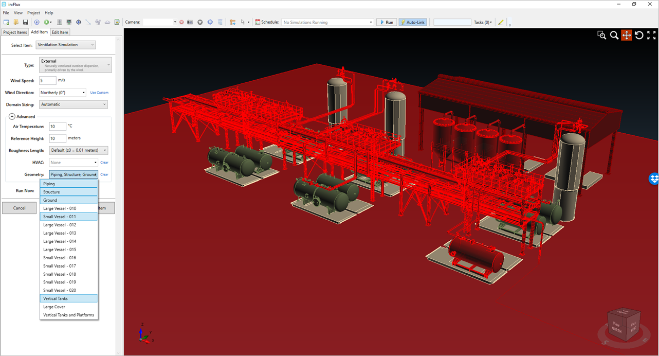
Geometry pieces that are selected will turn a transparent red color in the 3D window.
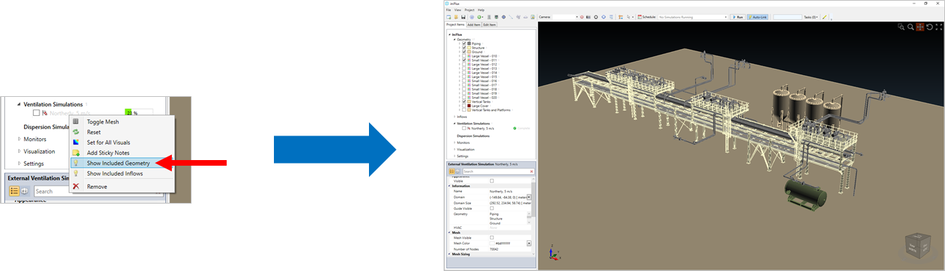
If you only want to show the geometry for the simulation in the main 3D window, just right-click on the simulation and select Show Included Geometry