Normalized Vectors and Magnification
When adding a vector field to a project from the Add Items tab, it is defaulted that the size of the vector shape is synced with the value of the velocity magnitude. Thus, small or lower flow regions will have smaller vectors that higher flow regions, as shown in the image below. Notice the flow around the tank is lower due to the re-circulation happening, so the arrows are much smaller than that of the arrows further away from the geometry.
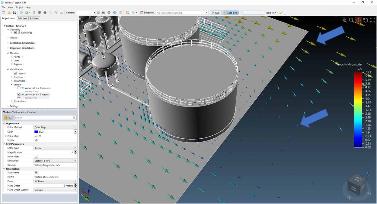
Tutorial 6 - Figure 81 - indication of different sizes of vectors for the automatically defined vector field
For some applications it may be desirable to have all the vectors be a larger size. This can be changed when initially defining the vector field or by editing the properties of an already defined vector field by changing the value for Magnification to be higher than 1. In the below example, a magnification of 4 was entered for the same vector field as the figure above.
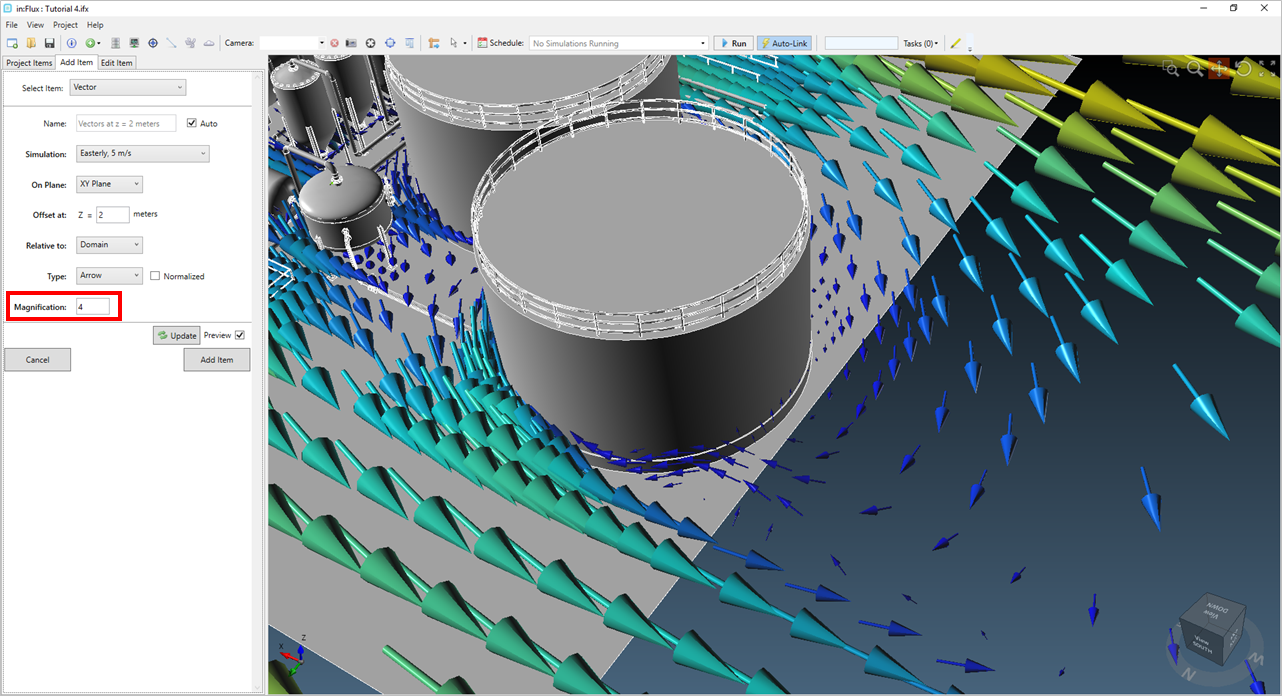
Tutorial 6 - Figure 82 - Options for changing the magnitude ("size") of the vectors from the Add Items Panel
With large vectors, overlap of the symbol can occur. An alternative to increasing the size of all the vectors is to normalize the vector field. For in:Flux, normalizing means changing the vectors to be all the same size. It is then the coloration that provides indication of the velocity magnitude value of each vector. You may normalize a vector field when adding it to the project from the Add Items tab or for an already defined vector field in the properties panel by checking the Normalize checkbox.
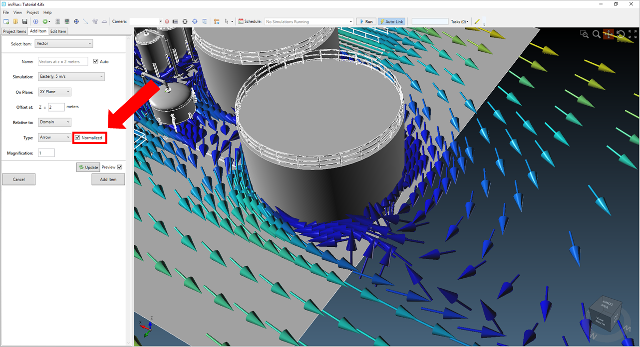
Tutorial 6 - Figure 83 - red arrow show the location for the Normalized checkbox.
You may choose to combine Normalized vectors with a Magnification to prevent overlapping of the vector symbols, as in the below figure with a normalized magnification value of 0.5.
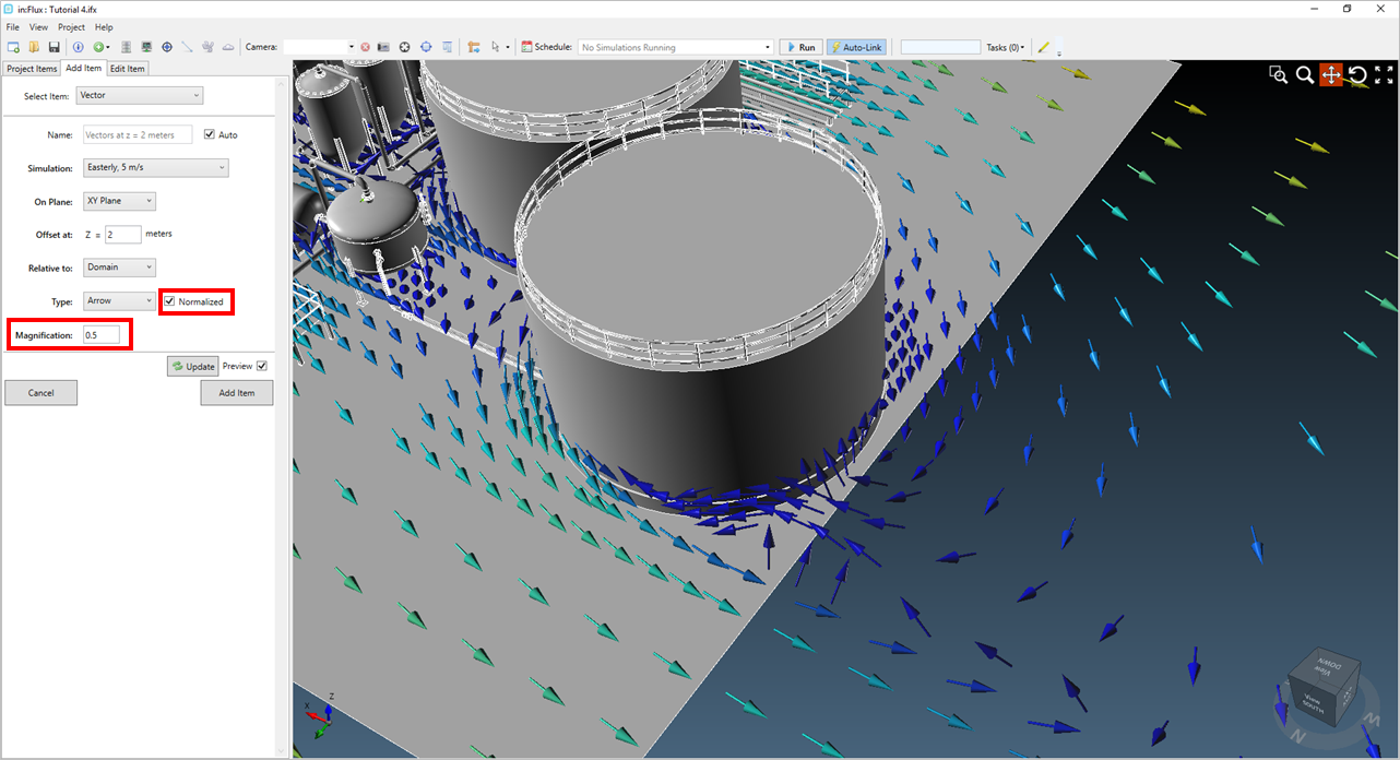
Tutorial 6 - Figure 84 - vectors appear best when using both the normalized option and the magnification option together