Displaying the Clip Plane
The clipping plane visually removes geometry and project items above a certain level, making it easier to see contours and other visualizations that may be obstructed.
Attributes of the Clip Plane:
-
Hides CAD above a defined plane
-
Can be defined on any of the three Cartesian planes (XY, YZ, ZX)
-
Can move dynamically by placing cursor in the offset textbox and pressing Ctrl+Up/Down for increments of ± 0.1 or Shift+Up/Down for increments of ± 1
The Clip Plane can be accessed from the View menu, toolbar ( icon next to the left of the Measure Tool icon) or right-clicking in the main
window. The plane can be changed by clicking the “Define Clip Plane” option of the View Menu which will make the following window appear. Click the Active checkbox to turn on the clip plane at the specified offset value.
The offset is measured from the origin.
icon next to the left of the Measure Tool icon) or right-clicking in the main
window. The plane can be changed by clicking the “Define Clip Plane” option of the View Menu which will make the following window appear. Click the Active checkbox to turn on the clip plane at the specified offset value.
The offset is measured from the origin.
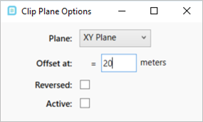
Tutorial 6 - Figure 53 - Clip Plane Window
In the below example a contour has been placed in the project where an offshore module's top deck hinders the view. In the right image, the clip plane has been activated on the XY plane to visibly cut the CAD pieces in order to better view the contour.
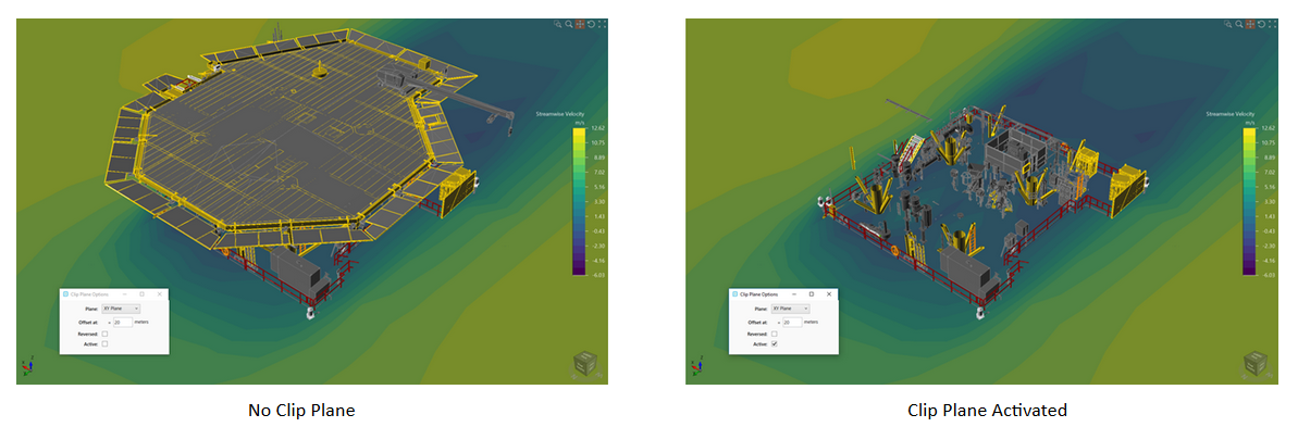
Tutorial 6 - Figure 54 - Before and after images of what happens when the clip plane is used.