The Viewcube and 3D Window Background Colors
ViewCube Usage
Maneuvering around large complex CAD geometries can become difficult. The view cube was added to facilitating moving around project geometries.
Not only does the view cube give indication of project north and other cardinal directions, but it also allows users to click on different faces or directions to move the 3D window to.
Each of the sides, corners, and faces of the view cube can be selected to change the view of the 3D window. The following figures show the resulting views for the selection of different parts of the cube:
- Face - selecting one of the faces will position the 3D window so that all of the currently visible project items can be seen while viewing the chosen direction. This is the same as using the view menu and selecting "top"
or "front".
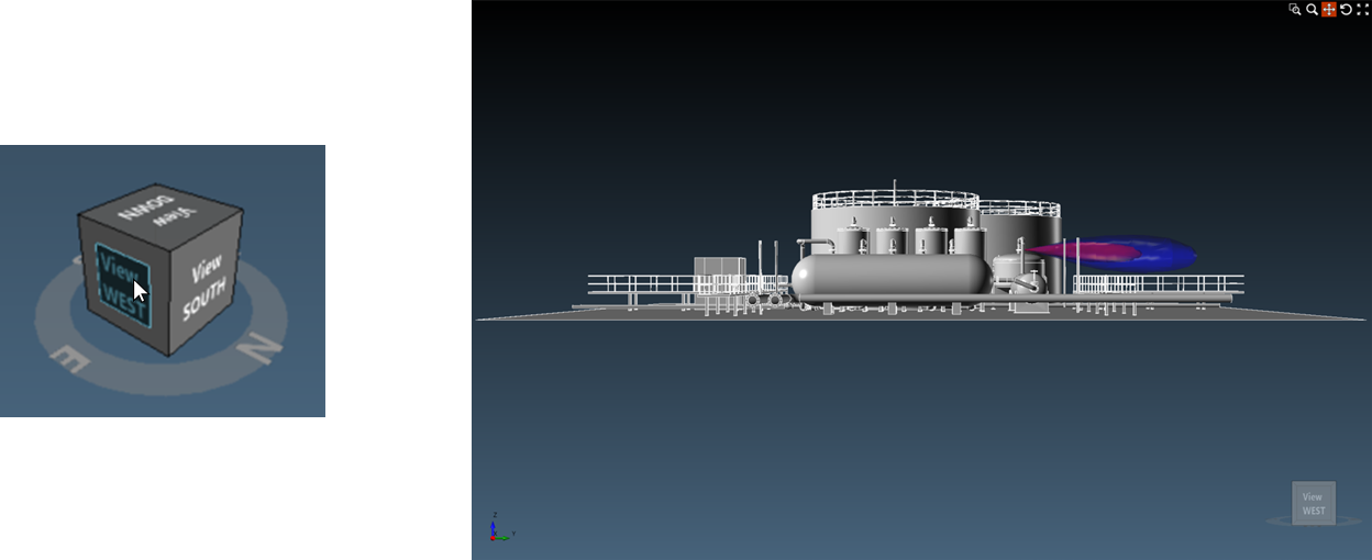
Tutorial 6 - Figure 38 - Showing selection of one of the faces of the view cube and the resulting 3D window
- Side (between two faces) - selecting one of the sides will rotate the 3D window so that the view would be looking at the selected side so that the two adjacent faces are visible.
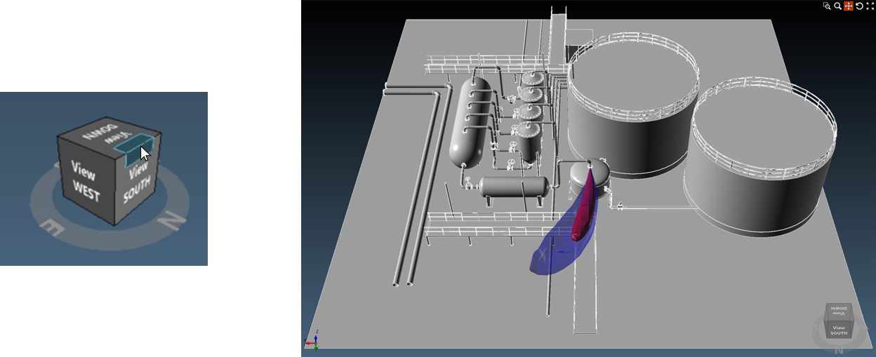
Tutorial 6 - Figure 39 - Showing selection of one of the sides of the view cube and the resulting 3D window
- Corner (between three faces) - selecting on of the 8 corners of the cube will move the 3D window to an isometric view so that the three adjacent faces are visible
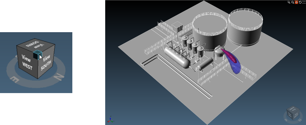
Tutorial 6 - Figure 40 - Showing selection of one of the corners of the view cube and the resulting 3D window
- Rotate - the ring around the base of the view cube can be clicked and dragged to rotate the entire 3D window about the Z-axis in the middle of the screen.
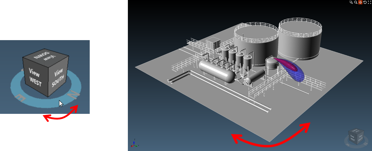
Tutorial 6 - Figure 41 - Showing that the base ring of the view cube can be selected.
View Cube Settings
The size (in pixels), color and visibility of the view cube can be changed by selecting the Application Settings in the Properties Panel.
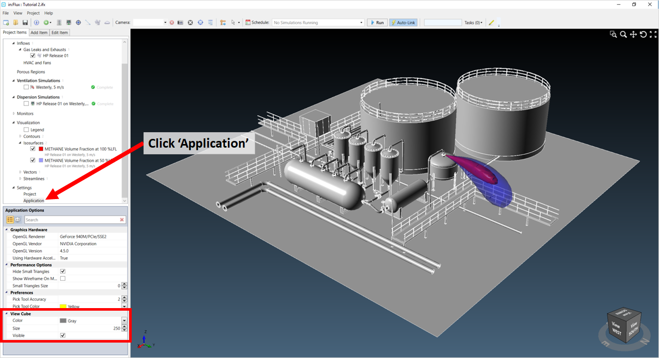
Tutorial 6 - Figure 42 - Where to find the Application Settings and View Cube options for in:Flux
3D Window Background Coloring
The coloring of the 3D window background can be changed from the Project Settings option under the Display header.
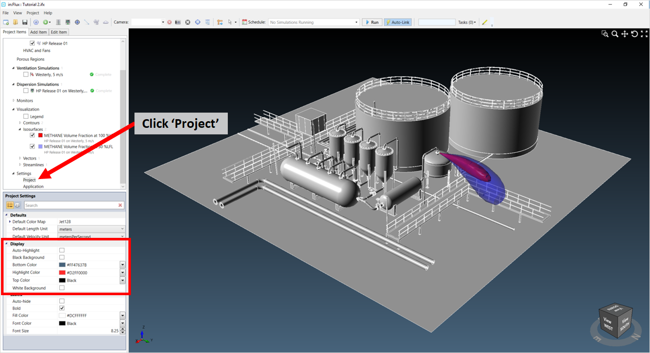
Tutorial 6 - Figure 43 - Where to find the Project Settings and Display options for in:Flux
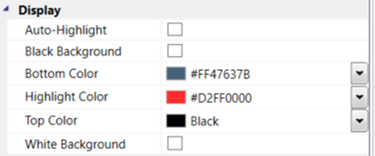
Tutorial 6 - Figure 44 - Larger View of Display Options
The top and bottom colors of the 3D window can be changed by choosing another color swatch from the dropdown menu in the Display section of the Project Settings. The gradient between the two colors will change depending on your selection. The image below shows that the Top Color has been changed from its default to "White".
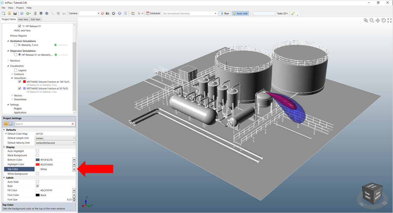
Tutorial 6 - Figure 45 - Indication of location to change the 'Top Color' of the 3D window
Alternatively, if you prefer to have a solid color, you may either select both the Top Color and the Bottom Color to be the same or choose one of the checkboxes for a white or black background, as shown below.
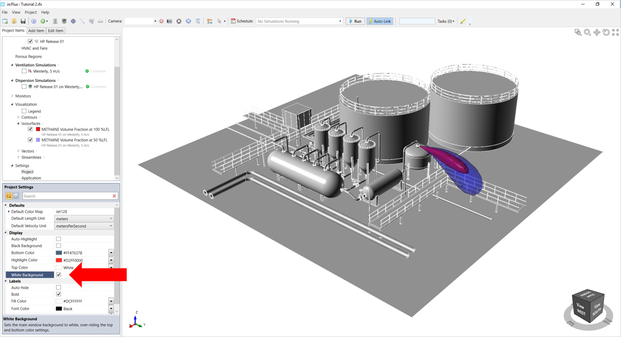
Tutorial 6 - Figure 46 - Indication of check-box to set the background of the 3D window to white
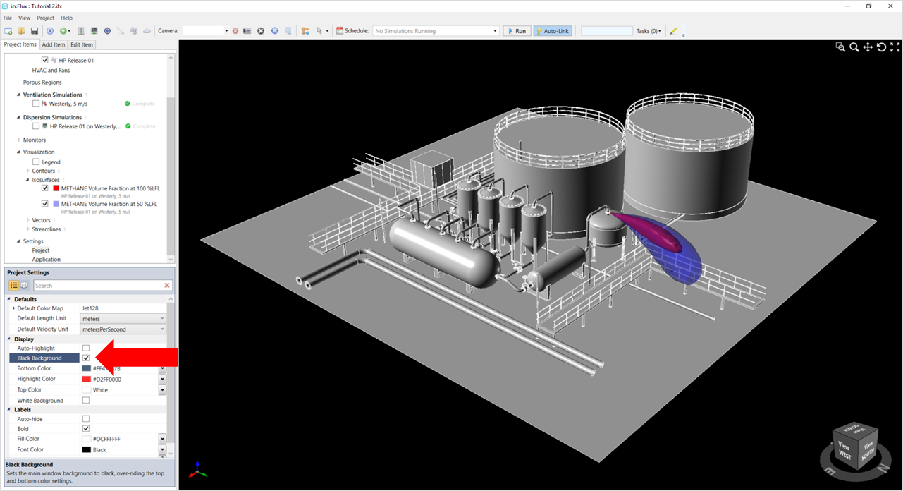
Tutorial 6 - Figure 47 - Indication of check-box to set the background of the 3D window to black