Inflow Definition with Multi-Component Gas
Once a gas mixture has been added or imported to the project it can be selected as the gas used for a high pressure gas leak or custom gas emission.
This tutorial will add a dispersion case with the created gas mixture and then determine if 100ppm of H2S is present on the walkways of the facility.
-
Click the Add Item tab and select Gas Leak or Emission from the dropdown menu.
-
Set the Type as High Pressure Gas Leak
-
Enter the Name to be "HP Release with H2S"
-
Click the Gas dropdown menu. The created gas mixture will be list at the top of the dropdown menu, scroll to the top and select the Mixture From Tutorial 7 and continue to Step 5. Alternatively, you may click the database icon
 and select the mixture from the Project Database Tab.
Tutorial 7 - Figure 11 - selection of the created gas mixture from the Gas dropdown menu when creating a new inflow
-
Leave the Upstream Pressure set to "10" bar(g).
-
Enter a value of "-20" C for the Upstream Temperature
-
Leave the Discharge Coefficient as "0.8".
-
Rather than use the hole size, click the Diameter dropdown option and select Mass Flow Rate then enter a value of "2.0" kg/s as the leak rate.
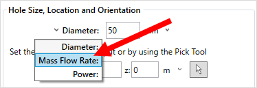
Tutorial 7 - Figure 12 - selection for using 'mass flow rate' as an input rather than hole size
-
For the inflow location:
-
In the Orientation section change the Pick Tool Rounding to Nearest 30°, as shown in Figure 13. This will enable the orientation of the leak to be closer to the normal of the point selected.

Tutorial 7 - Figure 13 - Showing where to change the 'Pick Tool Rounding' amount
-
With the rounding option selected, click the pick tool button
 next to the coordinate text boxes and zoom into the northernmost flange on the large horizontal vessel as indicated in Figure 14 and Figure 15 below or manually enter the coordinate "(9.96, 15.67, 5.5)".
Tutorial 7 - Figure 14 - Location to add the release, red arrows indicate approximate location, yellow arrow indicates direction vector
-
-
Ensure that the Angle from North is set to "-60" and the Elevation is "0" degrees.
-
Click the Preview checkbox to verify the inflow's location and orientation matches that of Figure 15.
-
Press the Add Item button

Tutorial 7 - Figure 15 - Preview of location and orientation of the HP gas mixture release
As the Westerly, 5 m/s wind has already been run in Tutorial 3 we will use this ventilation for our dispersion case. Recall that the westerly wind creates re-circulation regions near the process equipment as shown in Figure 16 below - dark blue areas representing negative flow. The HP Release with H2S has been pointed towards one of these stagnant regions to determine if H2S accumulates and if the walkways would contain levels higher than 100ppm of H2S.

Tutorial 7 - Figure 16 - View of Streamwise Velocity Contour and vectors for the Westerly, 5m/s wind at 5.5m height