Defining Leaks with the Risk Manager
Previous tutorials have defined releases one at a time from the Add Items tab, adding a single case or instance before adding another. Using the Risk Manager, individual or multiple leaks can be added, copied and edited in a tabulated view. Leaks added in this way are automatically added to the project.
There is no limit to the number of leaks that can be added to in:Flux project, typically risk-based projects with in:Flux have anywhere from 30 to 100 leak locations defined. For this tutorial though, only ten leaks will be defined. Time taken to properly define leak locations is time well spent, in most cases this is the longest part of the project (identifying equipment items and setting leak locations, directions, and frequencies). Refer to the Risk-Based Gas Mapping Workflow document for further guidance as needed.
-
Open the Risk Manager
 from the Project Menu if it is not already opened
 -
Click the plus icon (
 ) on the right side of the window. A new row will appear in the Risk Manager with columns representing
the properties of the leak. Each property can be edited by clicking in the cell, highlighting the current value and entering a new one.
) on the right side of the window. A new row will appear in the Risk Manager with columns representing
the properties of the leak. Each property can be edited by clicking in the cell, highlighting the current value and entering a new one.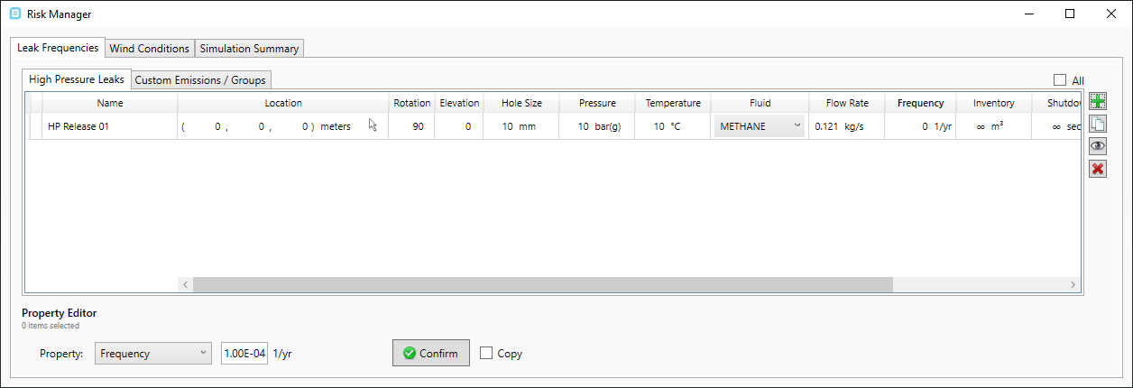
Tutorial 11 - Figure 07 - Risk Manager Window with a new leak added
-
By default, a newly added leak is positioned at the origin (0,0,0). Click the Pick Tool icon (
 ) in the cell associated
with the Location of HP Release 01 and the Risk Manager window will automatically minimize, allowing you to select the new leak location in the 3D window. Zoom into the section indicated below and choose the top of one of the
flanges as the leak location. Alternatively, you may enter the coordinates "( 54.92, 33.2, 16.3 )" in the corresponding location text boxes to match this tutorial.
) in the cell associated
with the Location of HP Release 01 and the Risk Manager window will automatically minimize, allowing you to select the new leak location in the 3D window. Zoom into the section indicated below and choose the top of one of the
flanges as the leak location. Alternatively, you may enter the coordinates "( 54.92, 33.2, 16.3 )" in the corresponding location text boxes to match this tutorial.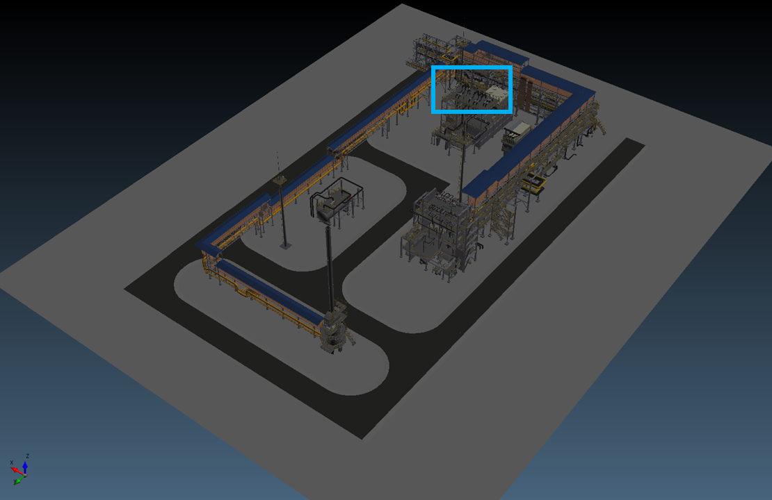
Tutorial 11 - Figure 08 - Indication of where to define the leak location (part 1 of 3)

Tutorial 11 - Figure 09 - Indication of where to define the leak location (part 2 of 3)
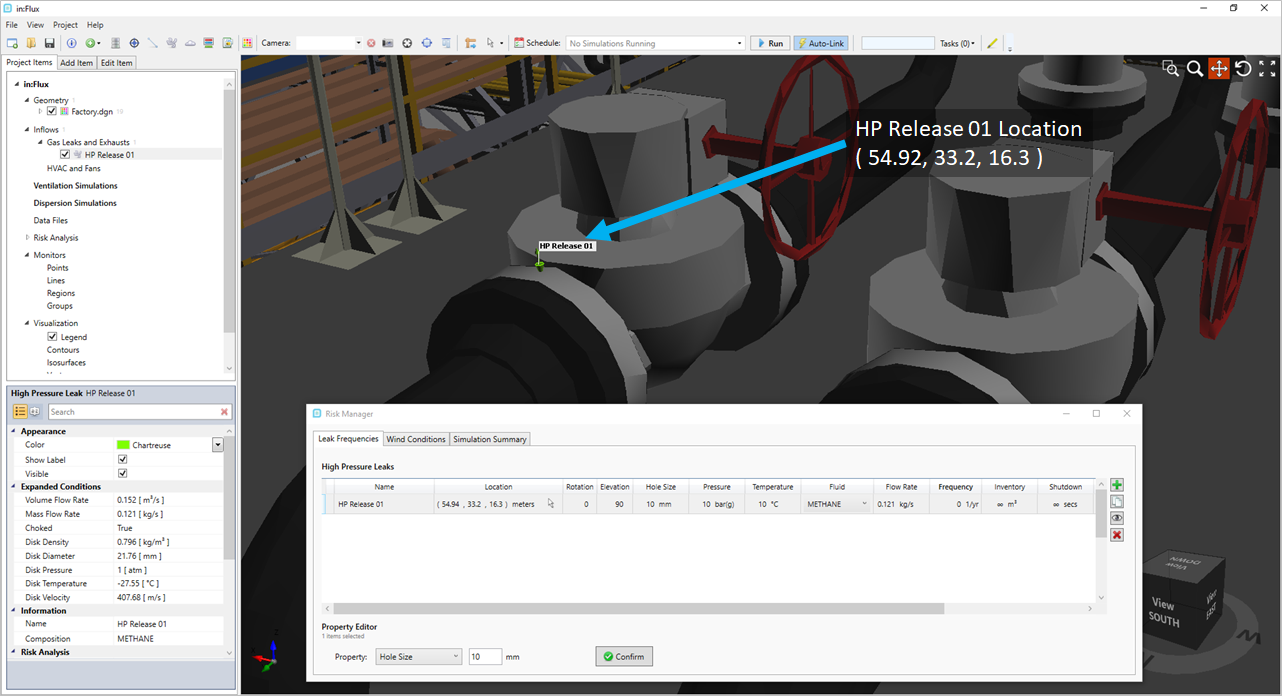
Tutorial 11 - Figure 10 - Indication of where to define the leak location (part 3 of 3)
-
Once a coordinate is selected with the pick tool the Risk Manager will re-appear. Ensure that the leak location is pointed up in the positive z-direction. This can be verified visually as in Figure 10 above but also by the values in the Rotation and Elevation cells for the leak - these should be "0" and "90" degrees, respectively. If you manually entered the coordinates, then you will need to manually enter the direction and elevation angles.
-
Note - the pick tool chooses the direction and elevation values to be in the normal direction of the CAD piece selected, meaning if the CAD piece between the two flanges is selected the leak may be pointed horizontally and in the wrong direction.
-
-
Now go through each of the cells in the row, entering the following information:
-
Hole Size: 30mm.
-
Pressure: 10 bar(g)
-
Temperature: 10 C
-
Fluid: Methane - this tutorial will be for a pure methane gas release. However, a multi-component mixture can be selected here if already defined. See Tutorial 7 regarding creation of multi-component mixtures.
-
The Flow Rate will automatically be set to 1.087 kg/s based on the hole size and pressure entered. You may opt to enter either a hole size or flow rate and the cells will update accordingly
-
Frequency: leave blank for now, this will be addressed in Step 9 below.
-
Inventory, Shutdown, Blowdown, BD Valve Size - leave these as the originally defined infinity values, representing a steady state simulation. Changing these values will make the leak to be a transient simulation. See Tutorial 8 for more information about transient simulations with in:Flux.
-
Group - leave blank as no groups will be defined for this tutorial
-
-
Select the HP Release 01 row to highlight it, click the copy button (
 ) on the right side of the Risk Manager. This will
duplicate the selected leak with its properties.
) on the right side of the Risk Manager. This will
duplicate the selected leak with its properties. -
Click the copy button (
 ) a second time so three leaks are listed in the Risk Manager as well as in the Project Items Tab
 -
Use the pick tool to define the locations of the two other leaks as shown in Figure 11 below. You may also manually enter the coordinates and angles listed below. Note: selecting the leaks in the risk manager will make it appear in the 3D window - to recreate Figure 11, all leaks were selected in the Risk Manager using Ctrl+A. Leaks can be defined immediately impinging on piping or other equipment but for purposes of this tutorial the leak locations were positioned on the exterior of the valve pair.
-
HP Release 02 - ( 55.22, 33.2, 16.08 ), Rotation of 90 degrees and Elevation of 0 degrees
-
HP Release 03 - ( 53.63, 33.21, 16.1 ), Rotation of -90 degrees and Elevation of 0 degrees
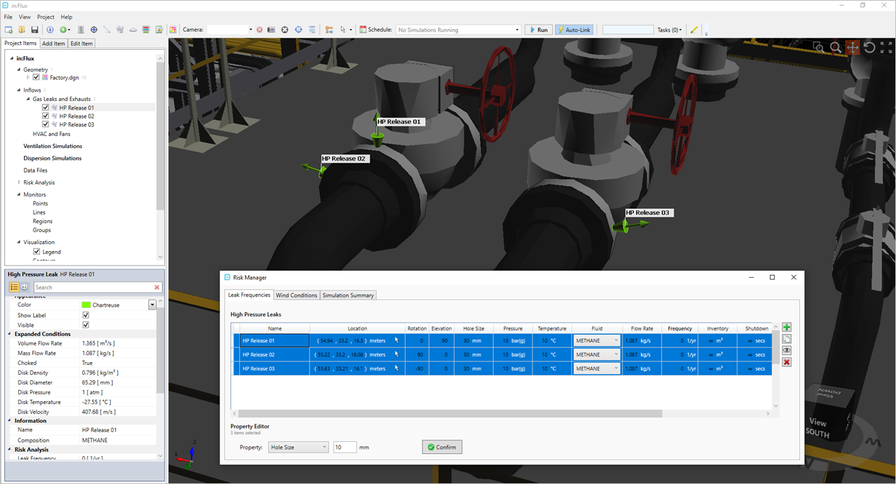
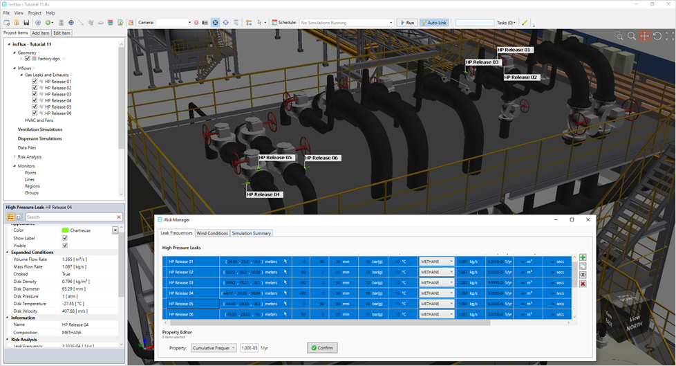
Tutorial 11 - Figure 11 - Definition of three leaks in the Risk Manager
-
-
When using the Risk Manager, a frequency can be defined to each leak independently or a cumulative frequency can be assigned to distribute a value over multiple leaks. At the bottom of the Risk Manager window is a Property dropdown menu. Clicking the Confirm button will assign the value in the text box to the property of the selected rows. Perform the following to assign a Cumulative Frequency to the leaks:
-
Select all three leaks in the Risk Manager
-
Choose Cumulative Frequency in the Property dropdown menu
-
Enter a value of 3.00E-03 and click Confirm. This data may be manually entered from various database sources, such as your own QRA, the OGP Risk Data, OREIDA etc.
-
-
Select all three leaks in the Risk Manager by clicking one and pressing Ctrl+A and duplicate them by clicking the copy button

-
Repeat Step 8 and choose a location for each of the three new leaks as shown below in Figure 12 or manually enter the following coordinates and angles:
-
HP Release 04 - ( 44.17, 29.33, 16.04 ), Rotation of -90 degrees and Elevation of 0 degrees
-
HP Release 05 - ( 44.42, 29.33, 16.3 ), Rotation of 0 degrees and Elevation of 90 degrees
-
HP Release 06 - ( 45.55, 29.32, 16.0 ), Rotation of 90 degrees and Elevation of 0 degrees
Tutorial 11 - Figure 12 - Risk Manager with 6 leaks defined, also shown in 3D window
-
-
The Frequency values as well as the Hole Size, Pressure, Temperature and Fluid do not need to be entered for HP Release 04, 05 and 06 as they were copied from HP Release 01, 02 and 03.
-
Continue by adding four more leaks to the vertical valve on the south side of the top platform as shown in Figure 13 below. Make use of the Add
 and/or Copy
  buttons that were used earlier. Alternatively, you may manually enter the following information
for the four new leaks all with :
buttons that were used earlier. Alternatively, you may manually enter the following information
for the four new leaks all with :-
HP Release 07 - ( 52.4, 29.59, 16.48 ), Rotation of -180 degrees and Elevation of 0 degrees
-
HP Release 08 - ( 52.18, 29.8, 16.49 ), Rotation of -90 degrees and Elevation of 0 degrees
-
HP Release 09 - ( 52.39, 30, 16.48 ), Rotation of 0 degrees and Elevation of 0 degrees
-
HP Release 10 - ( 52.6, 29.81, 16.48 ), Rotation of 90 degrees and Elevation of 0 degrees
-
Set the same hole size, pressure, temperature and fluid as before for HP Releases 07, 08, 09 and 10
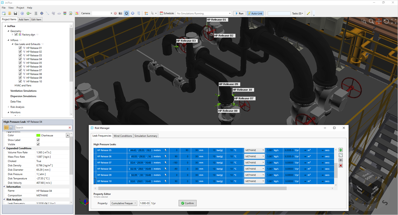
Tutorial 11 - Figure 13 - Risk Manager with 10 leaks defined, also shown in 3D window
-
-
As there are four leaks on the last flange, the frequency should be updated as the prior releases distributed the frequency across only 3 locations. To resolve this, select HP Release 07, 08, 09 and 10 and assigning a Cumulative Frequency of 3.00E-3 for the four leaks via the Properties option at the bottom left resulting in the window as shown below.
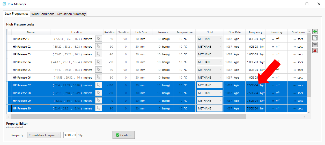
Tutorial 11 - Figure 14 - Risk Manager with 10 leaks defined with frequencies
You should now have 10 leaks defined in the project in similar locations to Figure 10 below. Notice that as releases are added in the Risk Manager, they are also added to the Project Items tab.
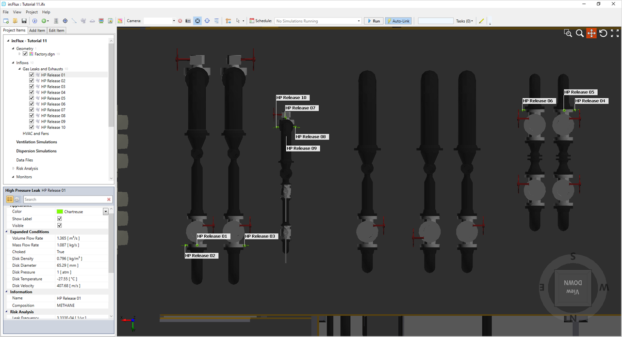
Tutorial 11 - Figure 15 - Top View of the locations of the 10 leaks defined with the Risk Manager of in:Flux
You should now have an understanding of adding, copying and editing leaks with the Risk Manager. This process can be repeated for several hundred leaks in a facility.
Custom Gas Emissions may also be added to the risk manager. In contrast to the above method, these inflows must first be defined via the Add Items Panel. Once defined they will appear in the Custom Emissions/Groups tab of the Leak Frequencies section of the Risk Manager.
Continue to the next section to define a wind rose for the example project.