Custom Gas Emission Definition
As opposed to high pressure gas leaks where a single point is selected and isentropic expansion is automatically calculated, custom emissions can be defined as any shape on a surface. This tutorial will go over selecting the top of a cylinder as the surface for the custom emission. See this section for other options available when defining non-circular inflows.
Zoom into the stern of the FPSO and find the three stacks in front of the helipad, as shown in the figure below.
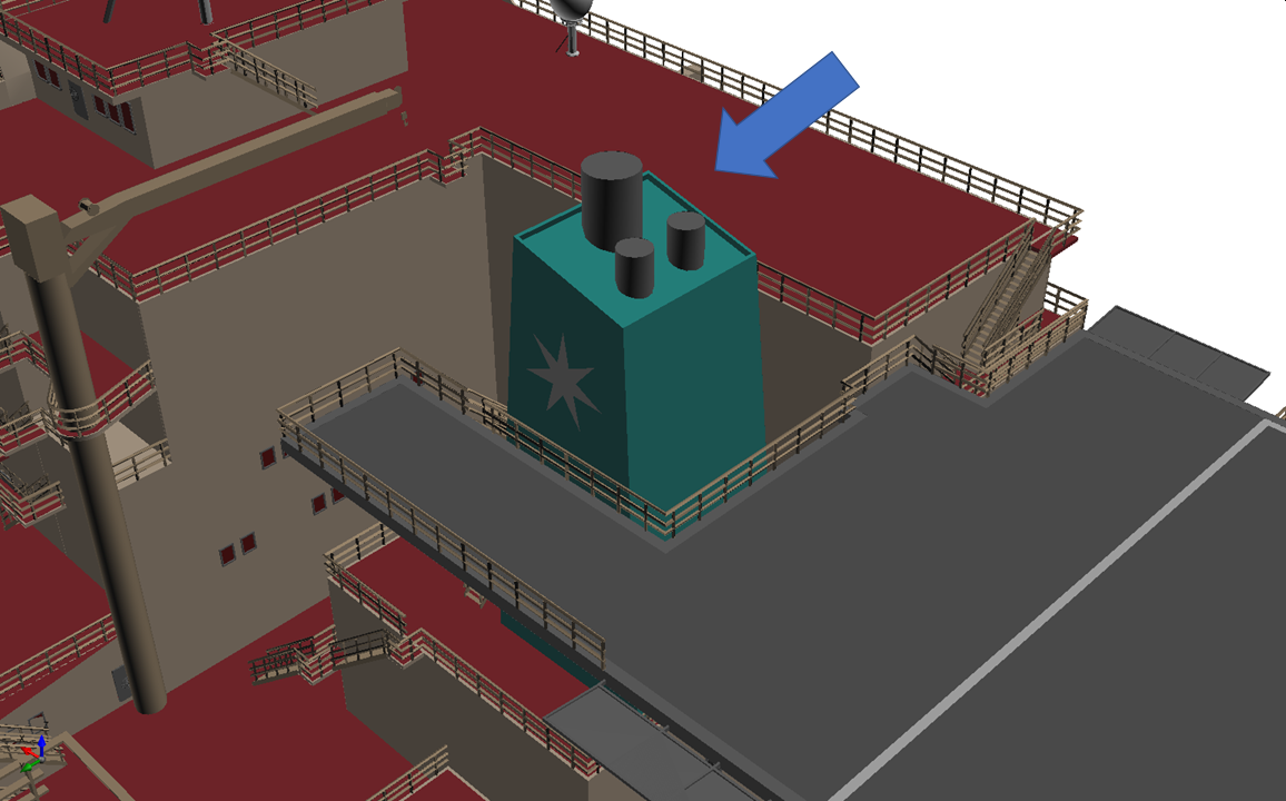
Tutorial 14 - Figure 05 - Three stack at stern of FPSO
Add the custom gas emission by performing the following:
-
Set the Select Item as Gas Leak or Emission from the Add Items Tab
-
Choose Custom Gas Emission as the Type
-
Give it a Name such as "Exhaust Inlet"
-
In the Gas dropdown menu, scroll to the top of the list and select the Exhaust defined in the prior section. Alternatively, the database icon may be selected and the previously defined Exhaust gas may be chosen from the Project Database Tab
-
Click the Velocity text to switch to using an input of Mass Flow Rate, as shown below. Then change the units from kg/s text to kg/hr. As most engine exhausts are provided in these units.

Tutorial 14 - Figure 06 - Selection to use Mass Flow Rate on Custom Gas Emission
-
Enter the Flow Rate as "21,000 kg/hr"
-
Enter the Temperature as "300° K", ensuring units have been changed from °C to K.
-
Rather than enter the diameter and position of a circle, we can select the triangles making up the top of the exhaust stack. To do this set the Selection to Planar and the Method to From Triangles. This will change the available options in the remainder of the panel.
-
Activate the Select Surface Pick Tool and while holding the CTRL key, click once on the top of the largest exhaust stack, as shown below. This will select the triangles making up the surface of the point selected and create an inflow to be the same size. Upon clicking the surface in:Flux will show a preview of the inflow.
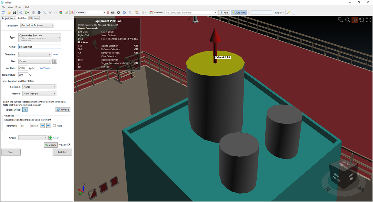
Tutorial 14 - Figure 07 - Selection of surface for Custom Gas Emission using equipment pick tool.
-
Click the Add Item button to add the custom emission to the project.
It may be the case, for some projects, that the inflow position chosen may be blocked by nearby geometry. in:Flux will give a warning when previewing the inflow if this is the case. To remove the warning, you may re-define the leak or if the leak is
below a CAD geometry surface, click once on the forward arrow button (![]() ) to increment the disc 0.1m in the direction the inflow is pointing. If the disc
was obstructed by geometry in the CAD model, it may cause an error in the calculation.
) to increment the disc 0.1m in the direction the inflow is pointing. If the disc
was obstructed by geometry in the CAD model, it may cause an error in the calculation.
Continue to the next section to setup the dispersion cases for the custom gas emission.