Defining a Custom Gas Emission - Any Shape
In most all cases, a pool fire base is not a perfect disc shape. This section will go over using the multi-pick tool to draw a unique shape representing a pool of liquid.
Start by choosing Gas Leak or Emission from the Add Items Tab:
-
Set the Type as Custom Gas Emission
-
Change the Name to Pool Fire Inflow - Drawn Base
-
Set the Gas to Heptane
-
Ensure the input variable is set to Power and enter "100MW" as the value.
-
Set the Temperature as "50°C"
-
For this inflow, change the Selection to Planar and the Method to From Points.
-
The multi-pick tool will appear (
 ), click it to activate the pick tool
 -
Using the left mouse button draw a convex shape on the ground near the other pool fire location defined previously, as shown below. With each click of the mouse a preview of the drawn shape will appear in red. After the first point is selected, the current mouse coordinate and the delta vector from the previous coordinate will be displayed by the mouse cursor. Keep watch of the z-coordinate value (blue arrow) as all the points should stay on the same plane, otherwise the surface will not be created correctly. Note: this CAD file ground is set to z=-0.04m, the inflow will be raise in Step 9 below.
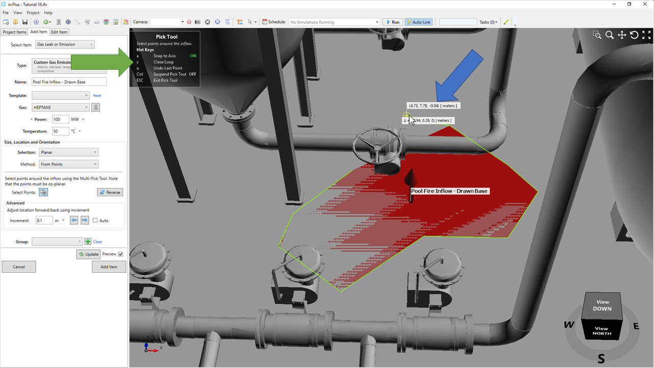
Tutorial 18 - Figure 03 - Drawing a custom inflow using the multi-pick tool.
-
Continue clicking points to create the desired pool shape until you reach near the first point selected and press "c" on the keyboard to close the shape. Various other hotkey options are available while the tool is active (green arrow in figure above).
-
Ctrl will suspend the pick tool allowing you to move around the 3D window without selecting a point
-
Press "u" to undo the last point selected
-
If you mess up or want to reset, press Esc. Practice doing this a few times while previewing the shape before continuing, ensuring that the elevation (z-coordinate) remains constant while drawing.
-
-
-
The arrow for the inflow should be pointed upwards into the ambient air. If the arrow for the inflow is pointed downwards into the ground, click the Reverse button (
 ), to correct the direction.
 -
If after Step 7 you cannot see a red preview of the drawn shape, or it looks patchy (meaning it is sharing the same elevation as another item), click once on the forward button (
 ) to increment the inflow location forward by 0.1m. You can also use this if the pool fire is drawn on CAD items below the ground height set for the ventilation case.
 -
Once you are happy with the size and shape of the drawn inflow, click the Add Item button.
You should now have an idea of how to define pool fires with the custom gas emissions inflow capability. The setup and review of the fire simulations are now the same as with jet fires.
Continue to the next section to define the two pool fire cases with the existing ventilation case.