Importing Images as Ground Objects
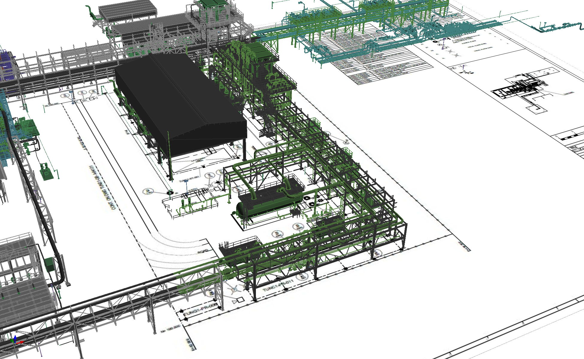
Google Earth screenshots or images of the environmental surrounding of a facility can be added to Detect3D or in:Flux projects for visualization purposes. Users may also choose to add plot plan drawings (example below) rather than environmental images.
The steps below will go over adding an HD image of the ocean surface to an offshore module.
-
Create and save an image or screenshot into jpg or png format
-
Load your project and right-click on Geometry and select “Create New Geometry”
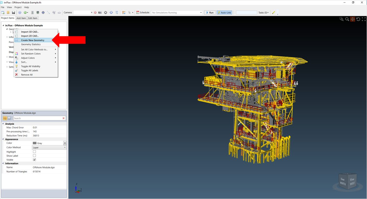
Selection of 'Create New Geometry' after right-clicking on the Geometry header
-
You will see the user interface for the geometry creation capabilities. This is where you can add shapes, delete entities, and add images etc.
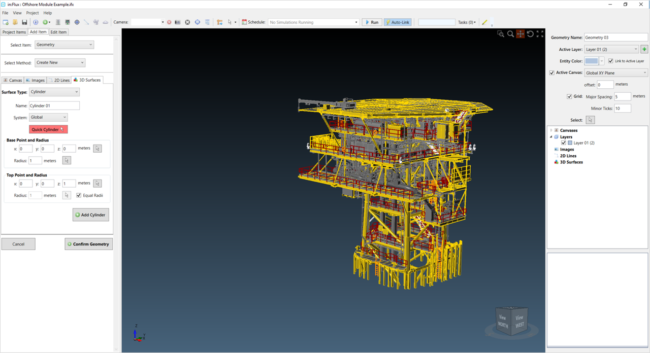
Create CAD interface
-
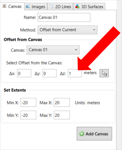
The first thing to setup is the “Drawing canvas”. This defines the plane to work on.
-
Select the Canvas tab on the left-side of the screen.
-
Enter a name for the Canvas or just leave it as "Canvas 01"
-
Specify the delta-z value to be the height of the plane which you want the image to be imported onto. This geometry has already been positioned so that the base of the CAD file is at a height of z = 0 meters which is the "ground" or ocean surface for this geometry.
Setting the height of the Canvas on which the image will be imported.
-
Right-Click in the 3D window and select the View From option as Top View. Change the Min X, Max X, Min Y and Max Y values to encompass the CAD file.
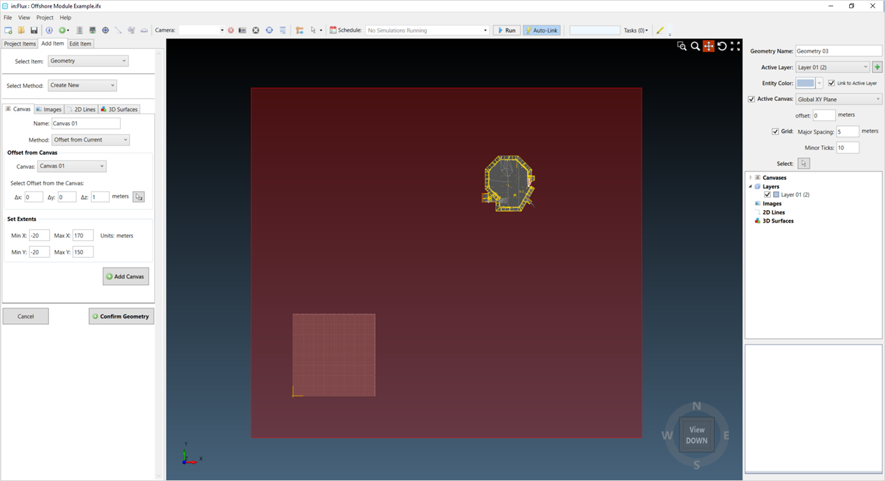
Setting the canvas to encompass the CAD model
-
Click Add Canvas
-
-
Now that the canvas has been defined, we need to make it "Active" so we can draw upon it. In the upper-right side of the screen, choose your named canvas from the Active Canvas dropdown menu.
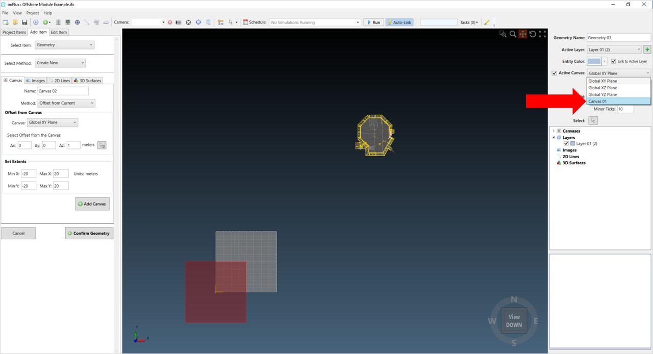
Selection of the newly defined canvas from the Active Canvas dropdown menu
-
Next, on the left side select the Images tab, click Browse to Image, and navigate to your saved image.
-
The image will be imported, but it will be positioned at the origin and scaled based on estimates from the active canvas – this is because the software does not know the real location or the size of the contents of the image.
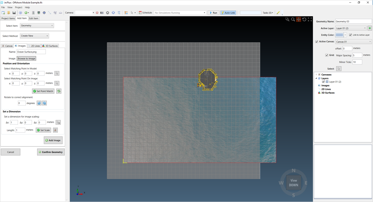
Ocean Surface Image has been added to the project but is not positioned in the desired location
-
You can see the canvas and grid overlays on the image – turn these off to make things clearer – uncheck the Grid checkboxes at the upper right of the window.
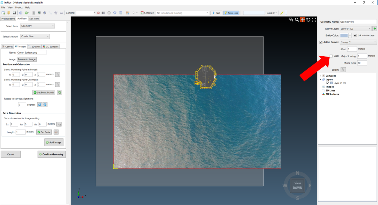
Toggling off the grid to make the imported image easier to see
-
Now the image needs to be scaled to the desired size. Since we are only importing this image for aesthetics, we want to make sure the image encompasses our geometry. However, you may want to import a plot plan drawing instead of a picture which requires the scale and positioning to be correct. For this image, the scale seems reasonable, but it is not encompassing the geometry. We can either scale the image to be larger or move the image in the positive y-direction. Note: each image import will be different depending on the origin of the imported geometry.
-
To scale this image, a value of 2 was entered in the Length text box in the Set a Dimension section. This doubled the size of the image as the delta vector was (1, 0, 0) with an original length of 1.
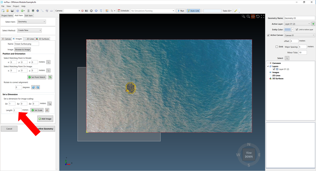
Indication of how to scale an imported image
-
Alternatively, to move the image in the positive y-direction, change the Y-value of the Select Matching Point in Model on the left side of the window to be the distance you want the image moved. For this example, the Measure Tool was used to determine that the image should be moved 50 meters. Once the value is entered click Set Point Match to translate the image.
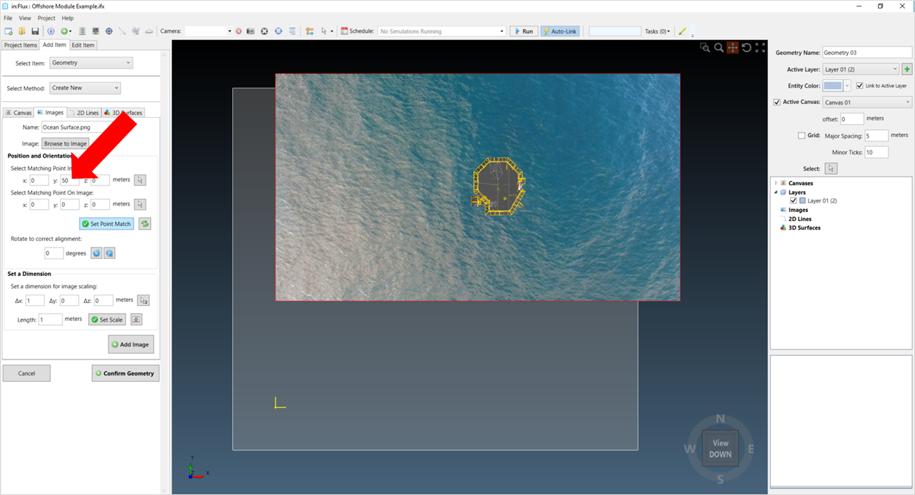
Showing where to translate the image in the positive y-direction
-
-
Regardless of the positioning method, once the image is in the desired location and with the desired scaling, click the Add Image button and then Confirm Geometry. Click OK on the warning message. You will notice that there is a new geometry listed in the project tree containing the imported image. You can toggle this on and off as with the other project items. As we did not add any CAD entities in this section, the image will not affect any calculations. You can rename the geometry from its properties panel.
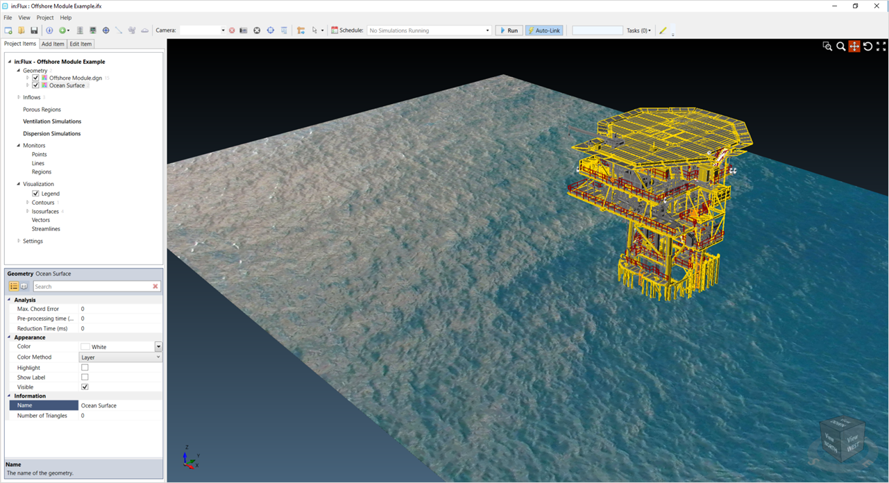
Showing the imported image of the ocean surface in the project