Creating a Polyline
We will now start outlining the walls of the hangar. The polyline tool will be used to make three lines which will later be triangulated and extruded to create the walls and rooms of the hangar.
It will be useful to change the Minor Ticks of the grid spacing as all the points in this tutorial will be integers and without decimals. To change the Minor Ticks, change the value of 10 to a value of 5 in the Minor Ticks: text box shown in Image 8 below. Setting the Minor Ticks to 5 places a grid point at single meter intervals, rather than the previous 1/2 meter intervals.
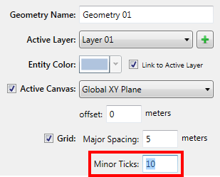
Image 8 - Minor Ticks text box - this should be changed to a value of 5
Click the topic below to expand the section:
Polyline 01Polyline 01
For the first Polyline:
-
Click the 2D Lines tab.
-
Polyline has already been selected for you as the Line Type.
-
Leave the name and units set to Polyline 01 and meters, respectively.
-
Zoom into the box indicated in Image 9 below.
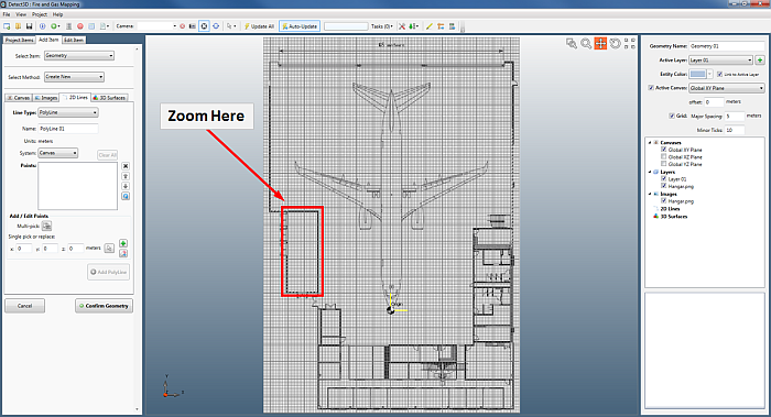
Image 9- Desired region to zoom into
-
Now use the Multi-Pick Tool button
 to choose the four corners of the room as shown in Image 10 below.
Notice the Pick Tool for Polylines has some more capabilities which are useful for closing the polyline ("c") or undoing the last point ("u"). The Pick Tool naturally snaps to the defined grid of the canvas. Grid spacing
can be changed from the Manage Project Panel.
to choose the four corners of the room as shown in Image 10 below.
Notice the Pick Tool for Polylines has some more capabilities which are useful for closing the polyline ("c") or undoing the last point ("u"). The Pick Tool naturally snaps to the defined grid of the canvas. Grid spacing
can be changed from the Manage Project Panel.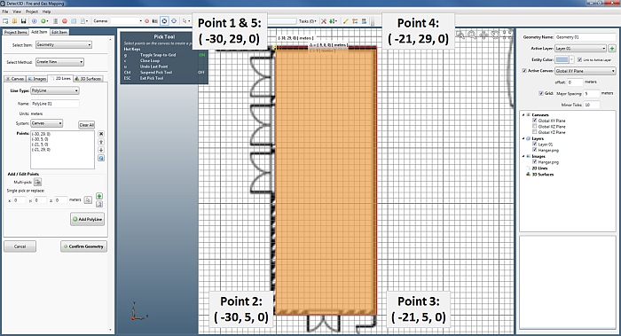
Image 10 - Displaying the region and points to select with the Multi-Pick Tool for Polylines.
-
The selected points will be automatically populated in the Points section of the 2D Lines Tab. Your points should be (or close to):
-
(-30, 29, 0)
-
(-30, 5, 0)
-
(-21, 5, 0)
-
(-21, 29, 0)
-
(-30, 29, 0)
-
-
Click Add PolyLine
Polyline 02Polyline 02
For the second polyline we will outline the rest of the rooms in the image as one single object.
-
In the 2D Lines tab.
-
Zoom into the bottom right of the image
-
Use the Multi-Pick Tool button
 to choose the corners of the room as shown in Image 11 below. Start
the polyline at coordinate ( -24, 5, 0) or near the bottom right corner of the previous polyline.
to choose the corners of the room as shown in Image 11 below. Start
the polyline at coordinate ( -24, 5, 0) or near the bottom right corner of the previous polyline.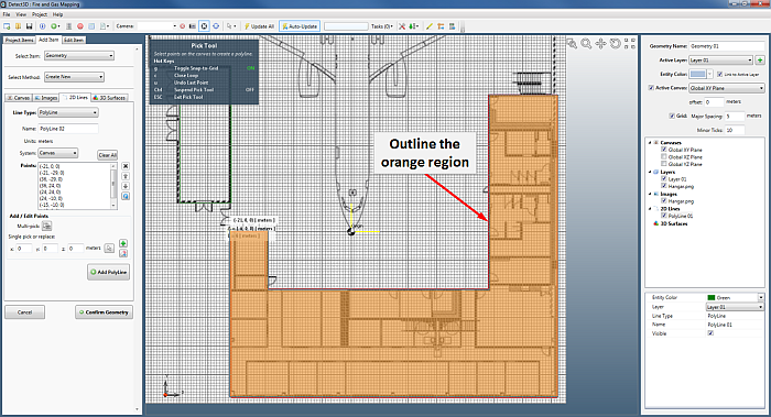
Image 11 - Displaying the Pick Tool for Polylines as well as the selected points for Polyline 02 (in orange).
-
The selected points will be automatically populated in the Points section of the 2D Lines Tab. Your points should be (or close to):
-
(-21, 0, 0)
-
(-21, -29, 0)
-
(36, -29, 0)
-
(36, 24, 0)
-
(24, 24, 0)
-
(24, -10, 0)
-
(-15, -10, 0)
-
(-15, 0, 0)
-
(-21, 0, 0)
-
-
Press Esc to deselect the pick tool.
-
Click the Add Polyline Button
For the final polyline we will outline the taller wall of one side of the hangar.
-
In the 2D Lines tab.
-
Zoom into the left side of the image
-
Use the Multi-pick button
 to choose the left wall of the hangar as shown in Image 12 below. Start the
polyline at coordinate ( -38, 73, 0) or the top right corner of the hangar.
to choose the left wall of the hangar as shown in Image 12 below. Start the
polyline at coordinate ( -38, 73, 0) or the top right corner of the hangar.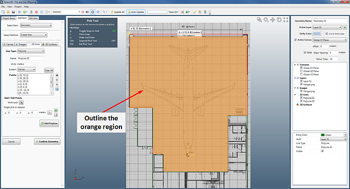
Image 12 - Displaying the Pick Tool for Polylines as well as the selected points for Polyline 03 (in orange).
-
The selected points will be automatically populated in the Points section of the 2D Lines Tab. Your points should be (or close to):
-
(-35, 73, 0)
-
(-35, 29, 0)
-
(-21, 29, 0)
-
(-21, 0, 0)
-
(-15, 0, 0)
-
(-15, -10, 0)
-
(24, -10, 0)
-
(24, 24, 0)
-
(36, 24, 0)
-
(36, 73, 0)
-
(-35, 73, 0)
-
-
Press Esc to deselect the pick tool.
-
Click the Add Polyline Button
We have now finished adding the three polylines to the geometry project. In the next section we will extrude the lines to make the three dimensional walls.