CAD Geometry Crop Tool
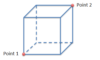
For managing projects with large CAD files, Detect3D and in:Flux comes included with a crop tool capability. The tool allows you to define a three-dimensional box, based on two points (shown below), and either keep the geometry inside or outside the box.
You have the option to crop a single geometry file or multiple geometry files at one time by selecting the All checkbox at the top right of the Crop Geometry window. Selecting the Save as Project Boundary option will save the dimensions of the cropping box so when you load a new CAD file it will be cropped to the set Project Boundary.
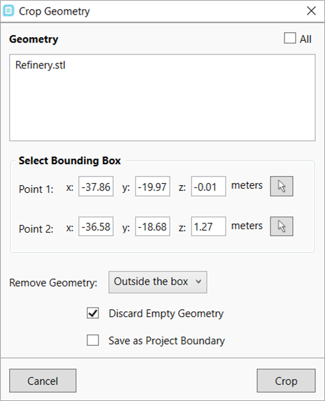
The Crop Tool can be accessed by clicking Project from the menu bar and selecting  Crop Geometry. A window (shown above) will appear which allows
you to use the Point Pick Tool to select two opposing points of the defined cropping box.
Crop Geometry. A window (shown above) will appear which allows
you to use the Point Pick Tool to select two opposing points of the defined cropping box.
Steps for Using the Crop Tool
-
Select Crop Geometry from the Project Menu.
-
Using the Refinery.stl file in the tutorials directory, select its name from from the Crop Geometry Window. Only the CAD items selected here will be cropped.
-
Set the two opposing points of the cuboid region in which you want to crop geometry. Note, placing the cursor in a text box and using Ctrl+ Up or down on the keyboard with increment the value by 0.1. Doing the same using the shift key will increment by 1.0.
-
This defined region can be used to either remove geometry pieces outside of it or to remove geometry contained within it. For this example set the Remove Geometry option to Outside the box.
-
Ensure that the checkbox next to Discard Empty Geometry check box is selected.
-
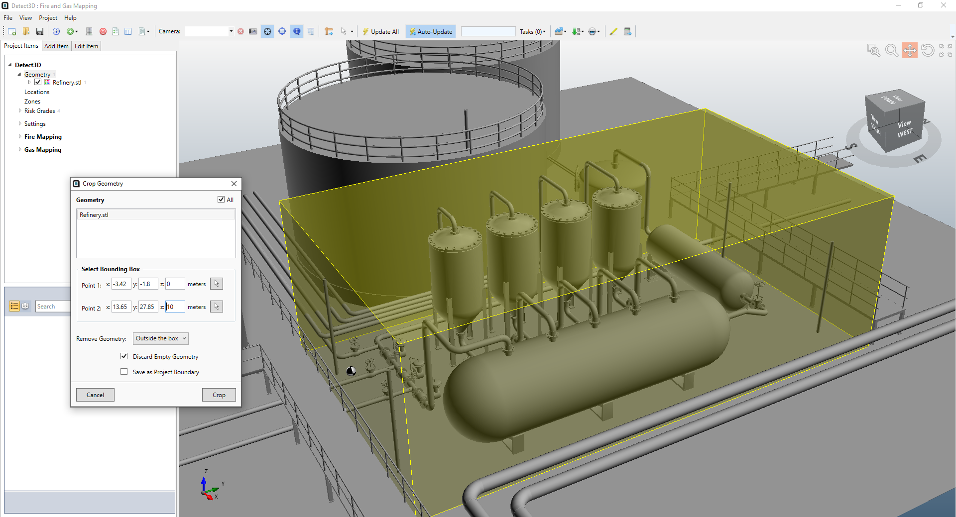
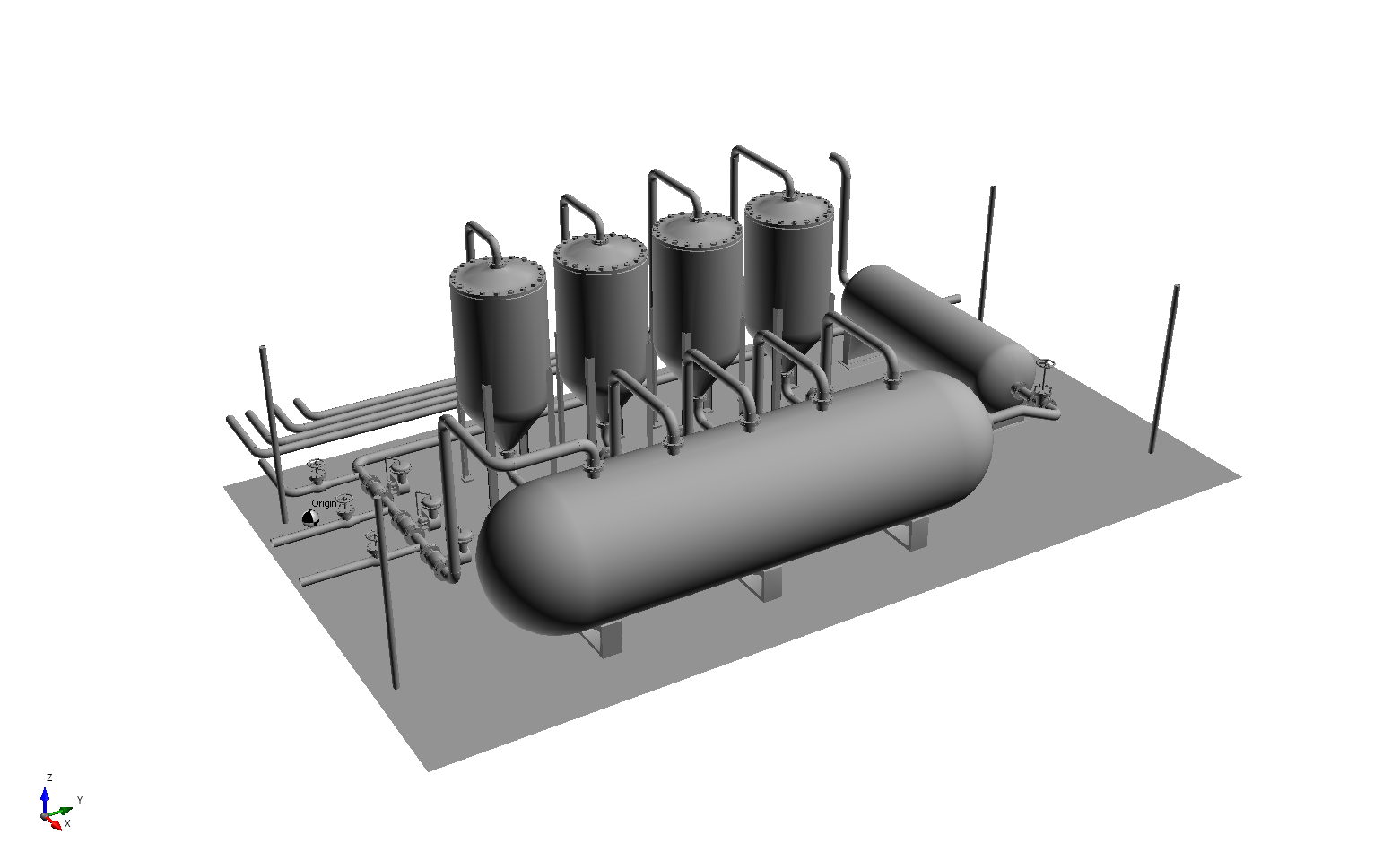
Click Crop. The two images below show a before (with the cropping cuboid region defined) and after with the geometry outside the defined region removed.