Multiple Fire Sizes for Multiple Voting Requirements
For fire detection mapping, some standards (such as NORSOK) suggest analyzing one fire size for 1ooN and another (typically larger) fire size for 2ooN. This section of the help guide will go over how to set this up in Detect3D using the Fire Area Method for geographic mapping.
In short, two physically identical zones need to be defined. One zone will be for the 1ooN fire size, while the other is for the 2ooN fire size.
Zone Setup - 1ooN
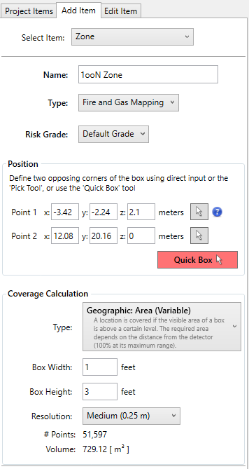
When zones are defined in Detect3D, the size of fire you are interested in studying can be entered when using the Fire Area Method. To do this, in the Coverage Calculation Section of the window set the Type to Geographic: Area (Variable). Options will then appear to enter the width and height of the fire you are analyzing. This example uses a 1ft x 3ft size, but other sizes and units may be entered, described later. The below image shows a screen shot of the zone definition window for the 1ooN zone. One the physical bounds of the zone and the fire size are entered, add it to the project.
Note that the height of the zone is only set to 2.1 meters. The defined fire area box (based on the entered Box Width and Box Height) is placed on top of all points in the zone. Meaning that at the top of the zone, the fire area box will extend above the zone by the height of the box (in the below example this is 3 feet). Similarly, the fire area box extends beyond the sides of the zone by the box width. You may opt to reduce the size of the zone to incorporate this effect, as for some applications such as offshore the fire area boxes may protrude above other decks (which will not be visible to the detectors). The 2-meter height chosen here is just for example purposes.
Zone Setup - 2ooN
If you are using v2.63 or later, you may select the Copy option for the created zone by right-clicking its name from the Project Items Tab, shown below. All dimensions and calculation methods will be retained in the copied zone. If you copy your zone in this way, then you will need to manually edit the Method option and the zone name in its Properties Panel to match what is listed below (for the 1m x 3m size).

Using the Copy option for copying the 1ooN zone for use for the 2ooN this retains the same dimenions of the zone and sub-zones (if chosen)
Alternatively, you can define the 2ooN zone manually by returning to the Add Item tab and using the pick tools to select the same coordinates as the 1ooN Zone, selectable coordinates will appear as small red circles in the 3D window (shown below).
For the 2ooN zone, again set the Type to Geographic: Area (Variable). For the below, the Box Width was set to 1 meter and Box Height to 3 meters. Use the sizes determined to be appropriate for your project.
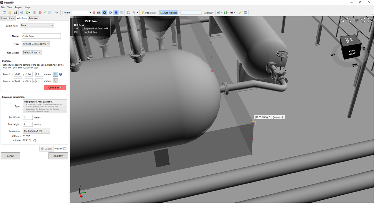
Manually defining the 2ooN zone by selecting the corners of the 1ooN Zone, also shows the entered 1m x 3m fire box width and height
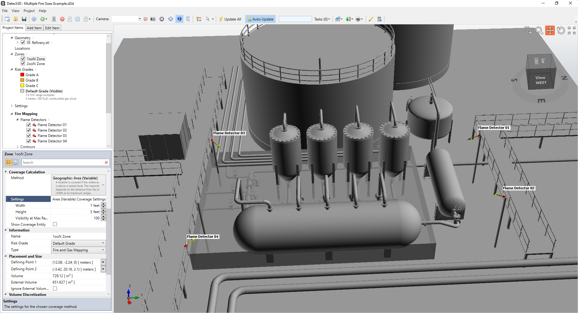
With the two zones now defined, toggle their visibility on and check each's properties panel to verify that their dimensions area the same. Flame detectors can now be added and coverage results will be calculated based on the fire area sizes entered. Four detectors have been added to the example below, the resulting coverage results table is also shown.
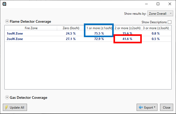
A blue box was placed around the 1ooN coverage result for the 1ft x 3ft fire size and a red box around the 2ooN result for the 1m x 3m fire size. These would be the values to report for the assessment. Typically, these projects will result in one coverage target being easy to achieve and the other quite difficult. Sometimes this is the 2ooN target, but the opposite is also possible.
Visualizations
Contours for this type of project are slightly more complicated than a normal Detect3D project. As there are two zones defined, one for 1ooN and one for 2ooN, two separate contours need to be defined for each.
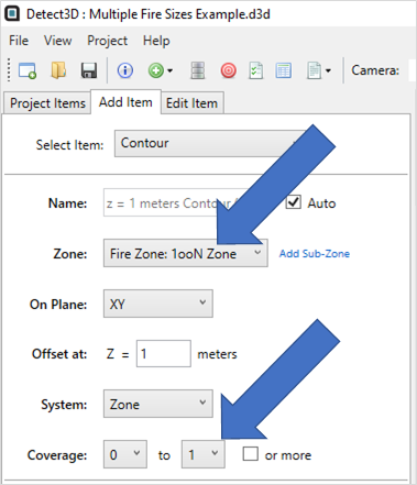
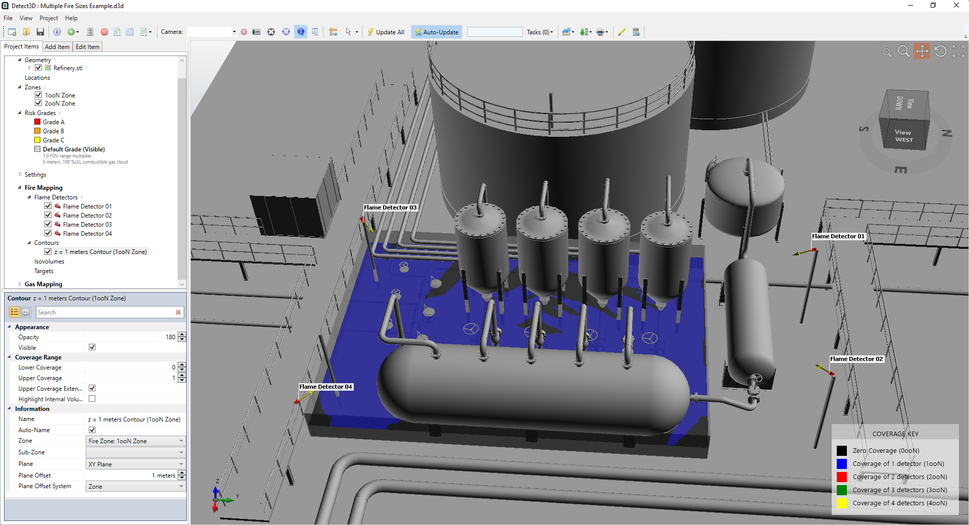
Starting with the 1ooN contour, choose the 1ooN zone and enter the desired offset height. The important part is setting the Coverage as 0 to 1. This will limit the contour to only show the 0ooN and 1ooN results for the 1ooN zone. The setup in the Add Item Tab and resulting contour are shown below.
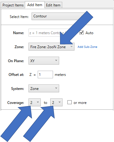
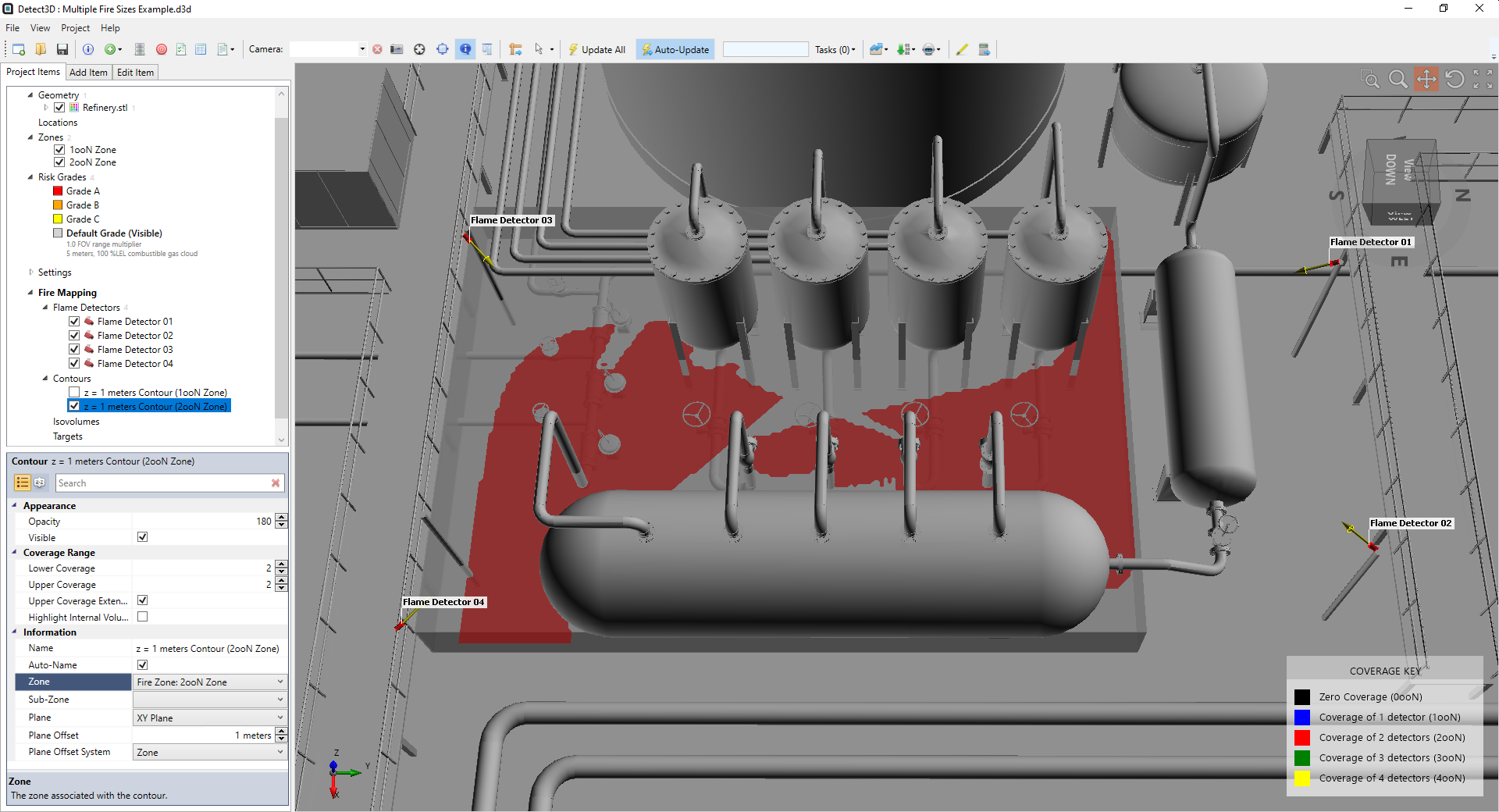
For the 2ooN contour, from the Add Items Tab choose the 2ooN zone and select the Coverage to be from 2 to 2. This will only display the 2ooN coverage for the 2ooN zone. The setup and resulting contour for the example layout is shown below.
Adding FOV Multipliers
Some users opt to edit the FOV multiplier of the risk grade when working with multiple fire sizes, since fundamentally the devices perform based on the amount of radiation getting to the lens as well as some other factors. For this example, two grades were made - one for 1ooN and a second for 2ooN. For the 1ooN Grade, the manufacturer's data was used so a FOV Multiplier of 1.0 was used. Note, this is the default value for the FOV Multiplier. Follow this link for a tutorial on how to create risk grades.
The inverse square law was used to then scale the maximum range of the provided manufacturer's data for the larger fire size of the 2ooN zone. This will vary depending on how you calculate the size or intensity of the larger fire. Some options are listed in the Society of Fire Protection Engineers Handbook, section 2. For example purposes an FOV multiplier of 3 was applied to the 2ooN risk grade.
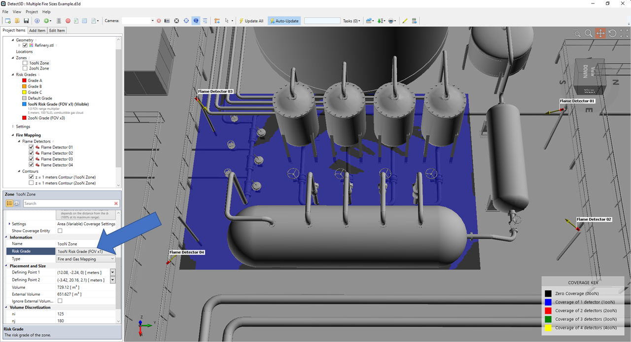
Once these risk grades are created, they then need to be applied to each's corresponding zone. This is done via the properties panel of each zone, as shown for the 1ooN zone below. To update the contour in the 3D window, right click the 1ooN risk grade and choose Make Visible.
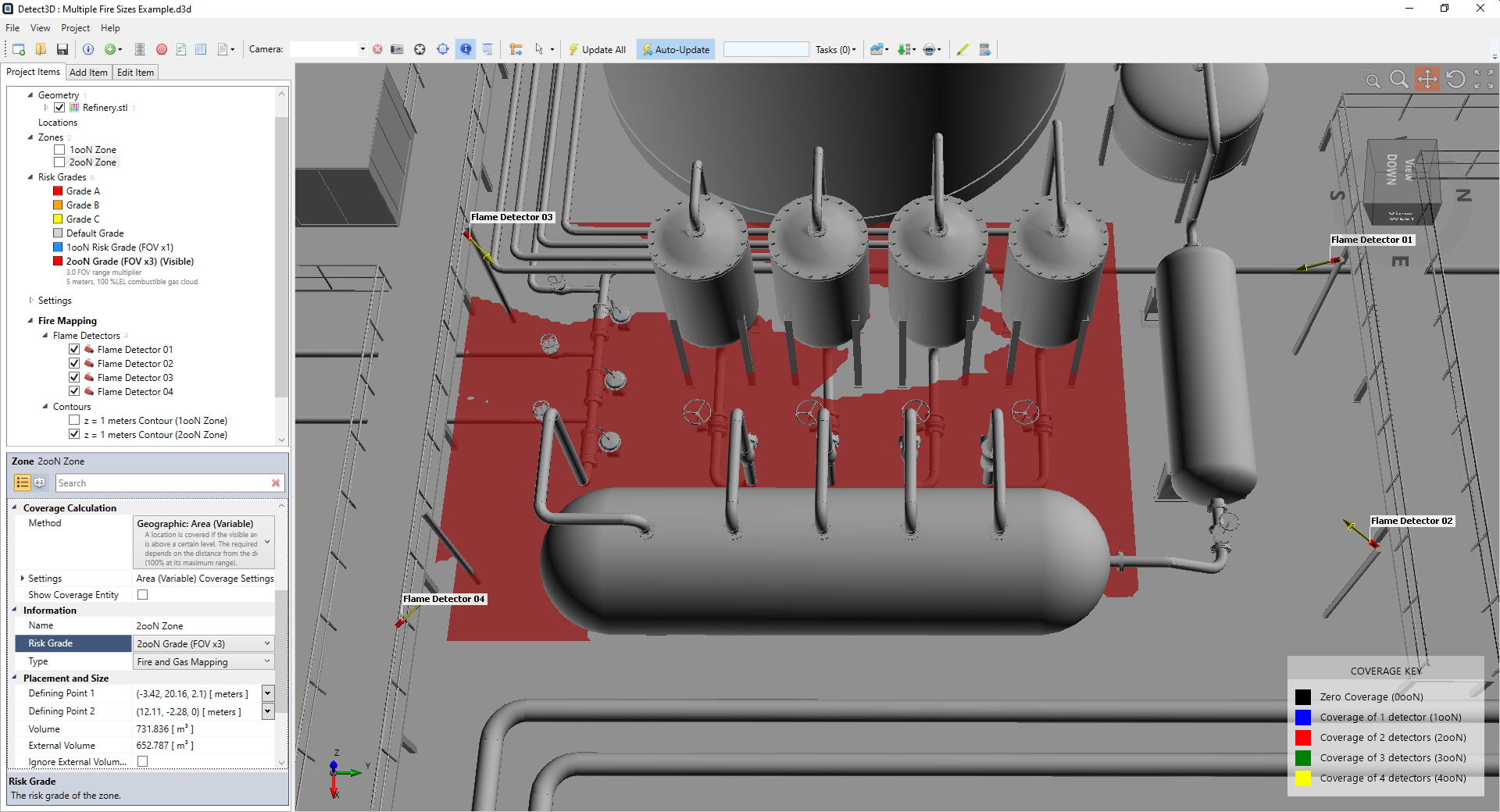
Repeat the same process for the 2ooN zone. The contour will be updated accordingly. The below image has made the 2ooN risk grade the Visible risk grade.
The coverage results will now be calculated with the FOV Multipliers applied.
