Fire Area Method vs Point Cloud Method
Detect3D allows you to choose between two methods for calculating coverage for flame detectors: the Point Cloud Method and the Fire Area Method.
The differences in coverage when comparing the methods can be significant as their approaches are fundamentally different. Choosing which method is best for you will depend on the project.
Ideally, for fire mapping we want to calculate the response of detectors to flames. Unfortunately, this is much harder than it sounds – to do this accurately would require us to know the full power spectrum from the flame, its modulation, information to account for attenuation and scattering, as well as the internal algorithms the detector uses to calculate if a fire is actually there or not (and not a false alarm source), which is proprietary. In other words, what seems simple, is in fact beyond our current engineering knowledge.
Furthermore, flame detectors are not tested for obstructed flames. The testing for FM 3260, which certifies ranges of devices, is done in completely unobstructed (ideal) conditions. We did not have any data about how flame detectors respond to obstruction until in 2019 when Insight Numerics and JGC did a joint presentation discussing the first experimental testing of this type at the FABIG TM99 meeting.
Considering all of the above, leaves us with quite a difficult situation because there is very little to go on when it comes to calculating coverage for obstructed fires. The best we can do is something sensible, but within that definition there are quite a few possibilities.
Point Method Calculation
The most obvious method is to calculate the region of a zone that is visible to a detector and divide that by the total volume of the zone. This is the “Point Cloud Method" or "Point Method”. The points are simply a discretization of space to help with this volumetric calculation. It is important to note that fires are not considered as points using this method. Points are just dots in space that help calculate the required volumes. We can change the discretization to be more refined (containing more points, e.g. resolution of 0.2 meter spacing) or more coarse (containing less points, e.g. resolution of 0.5 meter spacing).
The downside of the point method is that very small obstructions can add up for a large site to result in significant blockages to the detector. It would be impractical if you are performing analysis for a large fire (e.g. 1 meter base) that 1 inch pipes should be considered obstructions.
Fire Area (Variable) Calculation
This is where the Fire Area Method comes in. A user-defined surface is entered having a width and height - the Fire Area. Using the experimental data from the FABIG TM99 as a basis with the inverse square law, Detect3D determines the percent of the surface needed to be "seen" by the detector to go into alarm based on how much of the region is blocked. The result is that the closer the Fire Area is to the detector, the less it needs to be visible, because, like a fire, the intensity received by the detector will be greater.
A basic example is shown below describing how the distance away from the detector plays a part in this calculation. At the maximum range of the detector, 100% of the surface area of the defined fire area region must be visible for the detector to go into alarm.
If the distance between the detector and fire is halved, then by the inverse square law, only 25% of the original fire area region is required to be seen for the detector to go into alarm. In Detect3D the defined fire area is then positioned at all points in the zone. For each fire area coverage is determined by calculating how far away the fire area region is from each detector in the project as well as how much of it is blocked by obstructions.
Detect3D's Tutorial 13 goes over how to set a zone to calculate coverage using the Fire Area Method.
Fire Area (Fixed) Calculation Option
Rather than have the coverage acceptance of the Fire Area Region be determined in part by the inverse square law (distance the surface is away from the detector), users may enter a static value of acceptance criteria needed in order for the detector to go into alarm. Using this method ignores the distance the surface is away from the detector. To use this option, select the Geographic: Area (Fixed) as the calculation Method and enter a coverage percent for the amount of the box that needs to be seen.
Fire Area Calculations and Zone Heights
The fire area method still makes use of the point cloud for determining the location of each defined fire area. The point cloud here represents the base of the fire area region. The fire area is then positioned at all the points of the zone, at ALL elevations. Coverage is then calculated as described in the above sections. This means that if the analysis for a 1m x 3m zone is done for a 3m tall zone, then there are fire areas which extend upwards to 6m height (see the figure below). For example, projects with multiple decks having a zone defined to be the full height of the deck (with another deck above) would then have fire area regions extending above the above deck level. This may then allow detectors to see the zone below even if it is a plated deck. Due to this nuance of the calculation, some users opt to lower the zone height to accommodate the fire area's height.
Diagram for how the fire area region is positioned at ALL elevations of the zone (from the base of the zone to the top of the zone). Meaning the fire area can extend higher than the zone boundary.
Coverage Comparison Example
Which method to choose depends on your project. In general, it is good practice to start out with the Point Method. However, if the coverage is lower than expected, and the fire you are considering is much larger than many of the obstructions on the site, then the Fire Area Method may be helpful.
In general, the Fire Area Method leads to better coverage, however there are cases where the reverse is true. The following images show a comparison of the 0ooN isosurfaces for an example with five flame detectors.
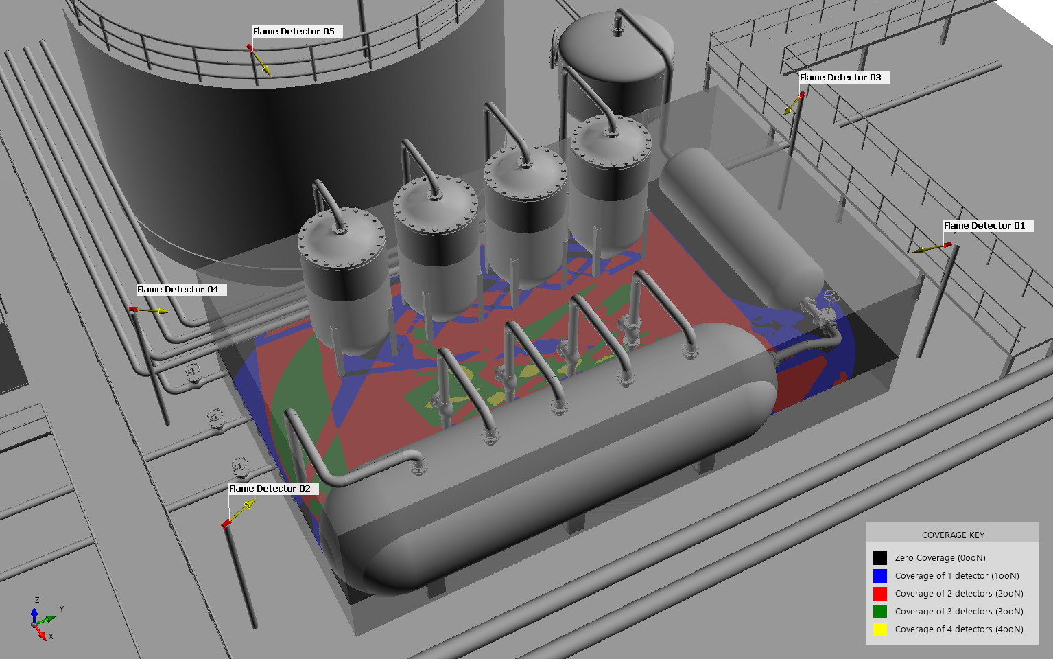
Original layout with cuboid zone defined and 5 flame detectors, contour at 1m height is also shown
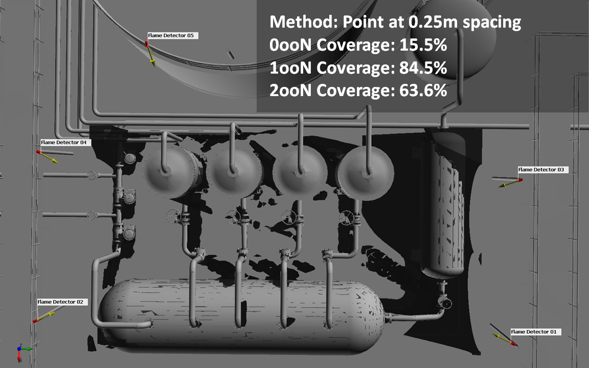
0ooN isovolume for point cloud method with 0.25m spacing of points, this is the default method used when adding zones in Detect3D

0ooN isovolume for point cloud method with 0.15m spacing of points
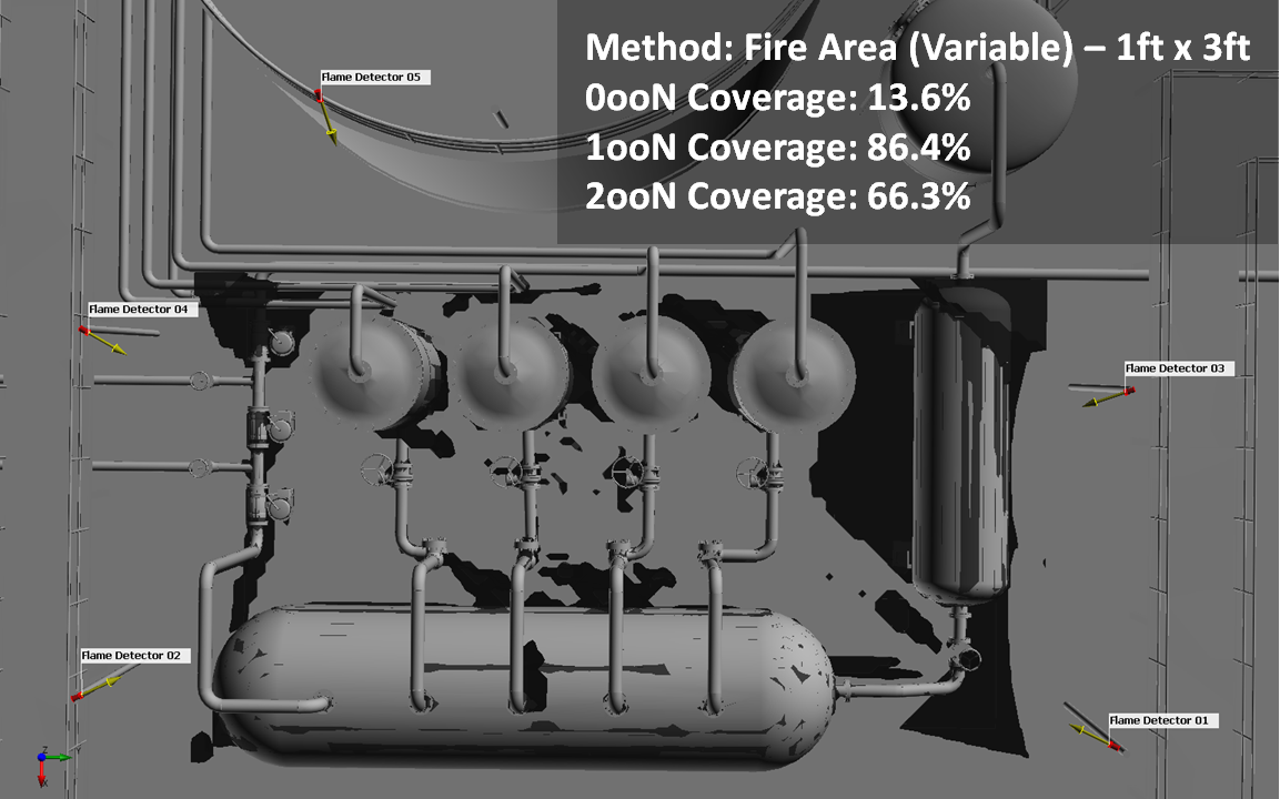
0ooN isovolume for fire area method using dimensions of 1ft x 3ft
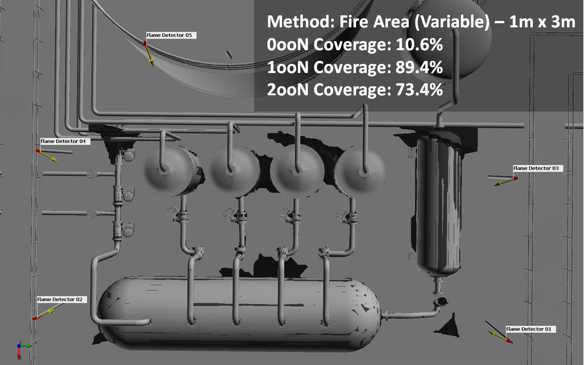
0ooN isovolume for fire area method using dimensions of 1m x 3m
Please contact us at info@insightnumerics.com for more information or if you have any questions regarding the above.