Setting Project North and Flame Detector Azimuth System
Project North
In most cases, the CAD geometry model will be correctly oriented. Some CAD software can change the orientation upon export which can affect flame detector azimuth angles. This may also be dependent on the site's method for how to represent north. TRUE NORTH could be used which represents the cardinal north direction, or a SITE NORTH may be used which will have an offset from the cardinal north direction. It is important to determine which your project is using when you receive the CAD file. This can be done by looking at the site plot plans and comparing to the CAD geometry.
Detect3D's viewcube can be used to help determine which direction is north in the model. Clicking the "View Down" text will display the model from a top view and orient the screen with North at the top. If this matches the plot plan then continue on with the mapping assessment. If this differs from the plot plan north, then two options may be taken, the second option is recommended as it is easier and quicker to implement and can be done after the analysis is complete:
-
Rotate the CAD model to match the site north direction. Note, this may change the coordinates of equipment and thus placed detectors so be careful when choosing this option. Think of this option more as rotating the geometry in the Detect3D coordinate system rather than the coordinate system rotating to match the geometry. Follow the below steps to rotate your model. This should be done prior to adding zones or flame detectors:
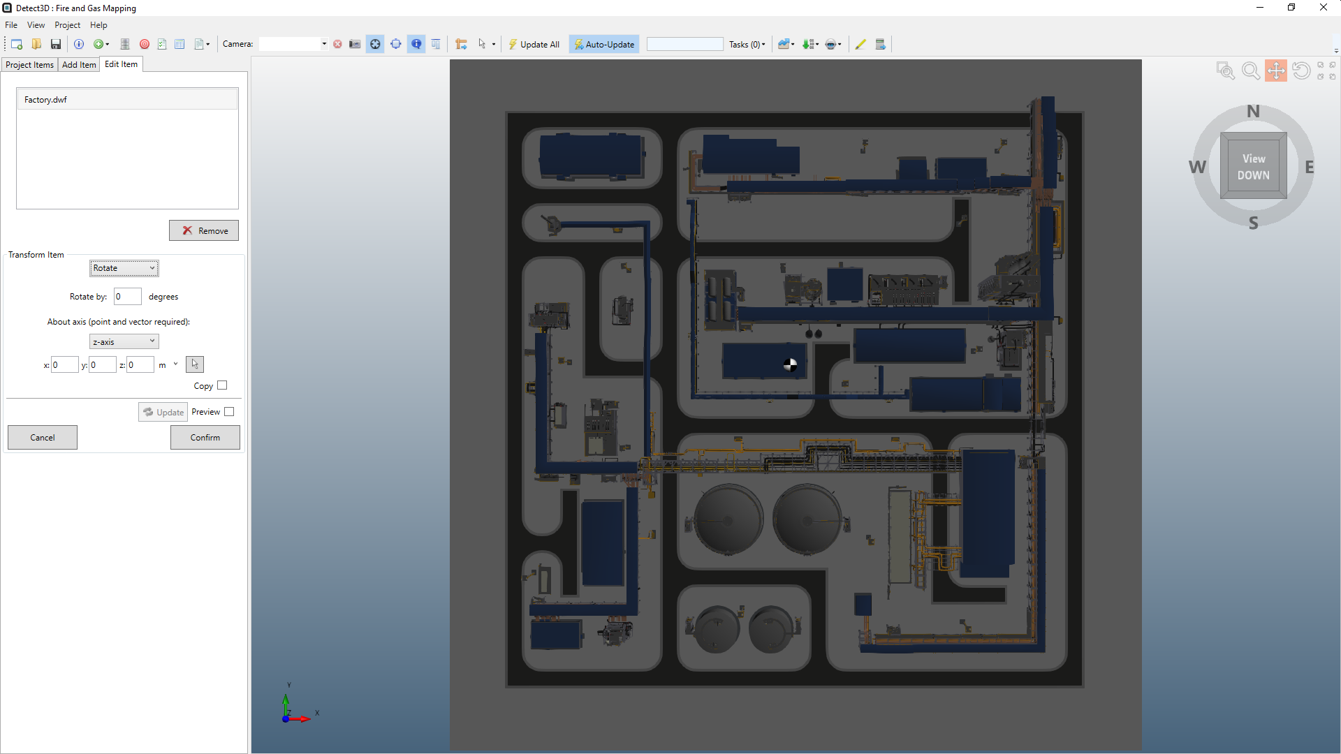
- With the CAD geometry imported, go to the Edit Items tab
-
Set the Transform Item to Rotate
-
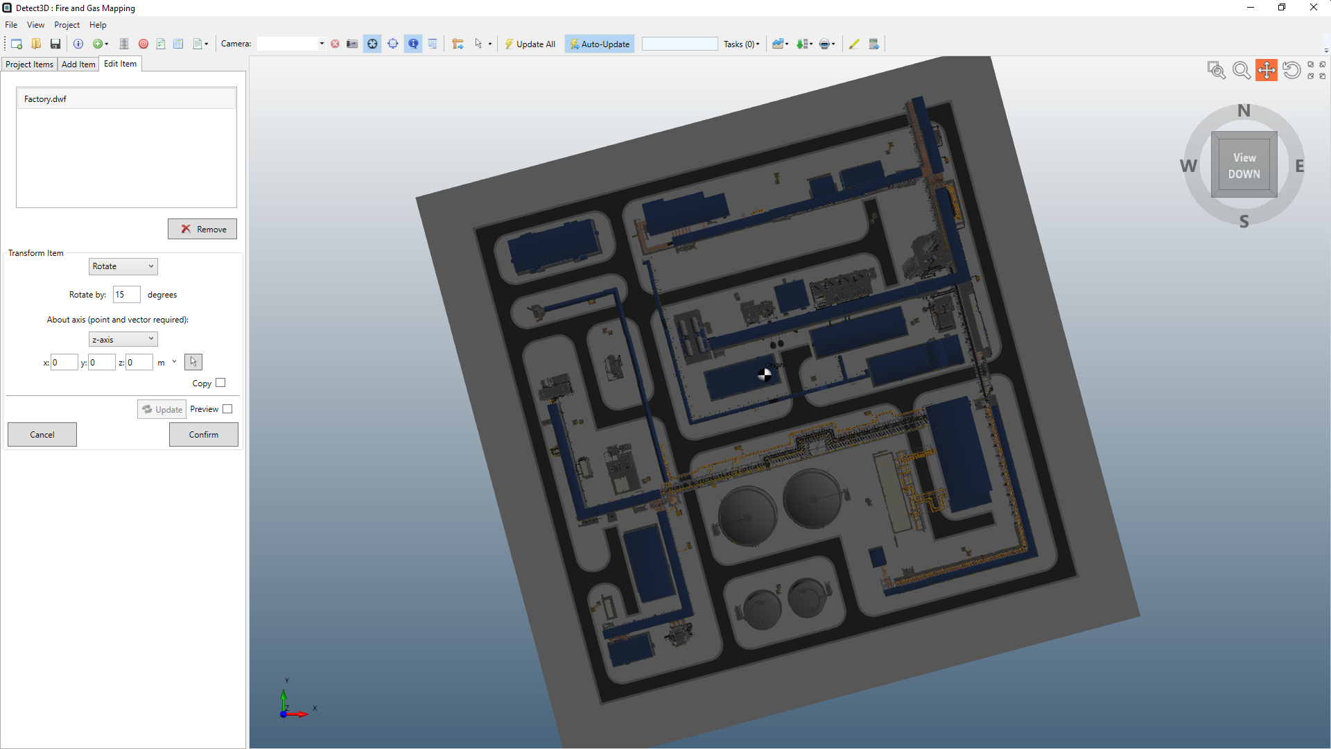
Enter the offset angle to rotate the model, for the below example 15° was used. A positive value here will rotate the model anti-clockwise around the defined coordinate axis.
-
Set the coordinate point to rotate the model around, this is normally the origin but you may have a reference point for a piece of equipment or structure item
-
Click the confirm button
-
After some processing the model will be rotated by the offset angle about the coordinate point entered. To reverse this, enter an equivalent negative angle.
-
Perform the entire mapping assessment with the CAD model as is. Determine the offset angle of the plotplan vs the model and then apply that offset angle to each of the flame detectors. This can be easily done in the Excel export Detector Layout Report. Using this method may also be combined with editing the flame detector azimuth system, described below.
Flame Detector Azimuth System
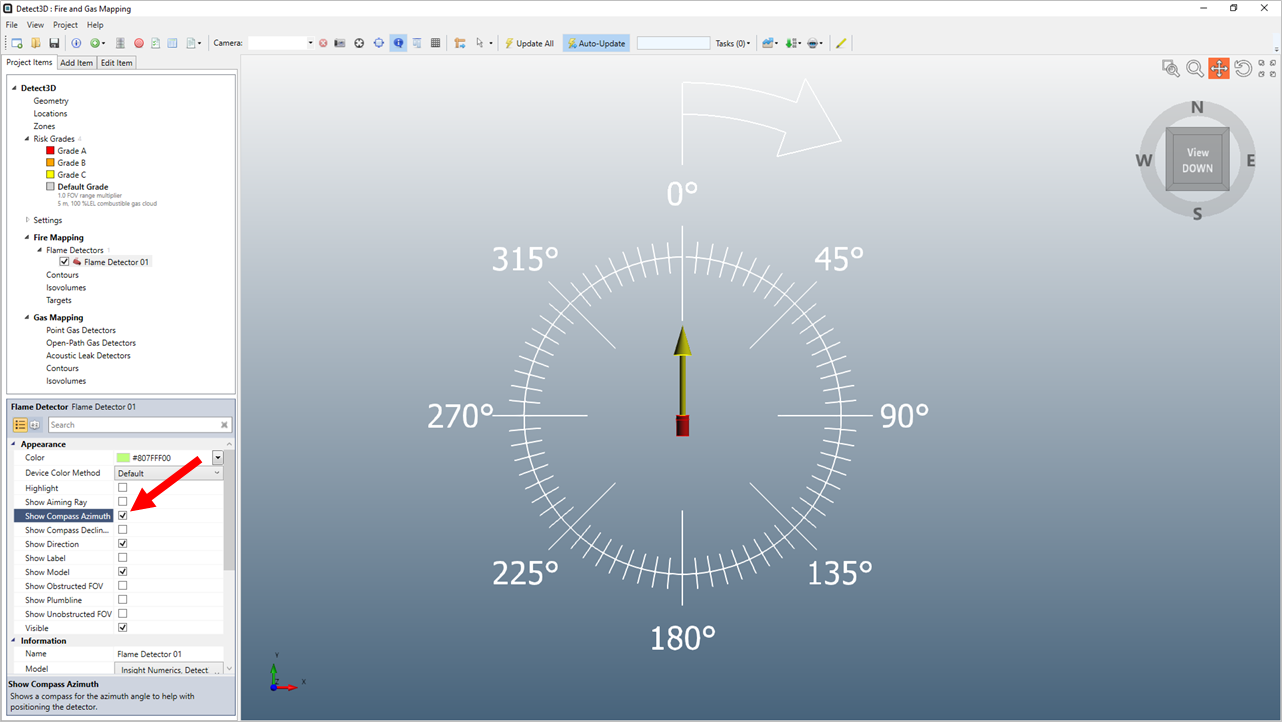
As of version 2.60, the Detect3D azimuth system for flame detector azimuth system was updated so that 0° azimuth points in the NORTHERN direction, or positive y-direction. The azimuth angle then increases when rotating Clockwise, as shown below, when looking at a detectors compass azimuth. This is different than in past versions. The azimuth system will only be applied to new projects, leaving existing project files to have the older system (Eastern direction being 0°, and anti-clockwise increasing values).
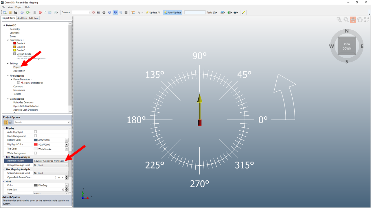
If needed, your project may use an alternative system for the azimuth angles of flame detectors. To edit this system, go to the Project Settings. Below shows the Azimuth System option being set to Counter-Clockwise from East. Choosing this option will automatically update the angles of all the flame detectors in the project to reference 0° as in the positive x-direction and increasing when rotating counter-clockwise.