Placing Point Gas Detectors
Three point gas detectors will be added to this project, positioned near the middle tank of the geometry.
-
From the Add Item tab, select Point Gas Detector from the dropdown menu
-
Set the Name of the detector as "Point Gas Detector 01"
-
Leave the Type as Combustible, and the Low Alarm and High Alarm as "10% LEL" and "20% LEL", respectively. These values to not affect the analysis for point gas detectors in Detect3D but can be used to record the alarm settings to be printed on exported reports.
-
Enter the coordinates ( 10, 8, 3 ) into the x, y, and z fields for the Location of the detector.
-
Click the Preview check box to see that the detector is positioned near the south-east side of the middle tank, shown below.
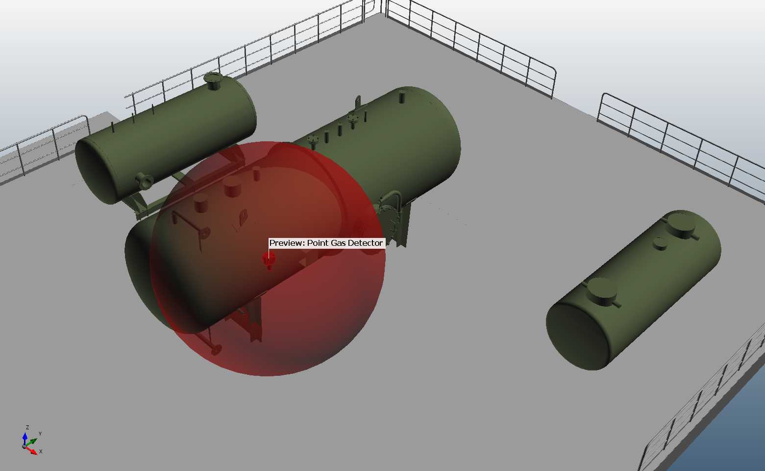
Tutorial 2 - Figure 02 - Position of Point Gas Detector 01 after entering specified coordinates
- Under the Array section ensure the Spacing is set to "5 meters" and change the Number in x: to 1 and the Number in y: to 2 from the dropdown menus. This capability can be used to quick define a 1-dimensional or 2-dimensional array of point gas detectors at the entered spacing as this method is suggested by some standards. If using this feature, the array of devices will be added in the positive x and positive y directions from the coordinate entered in the Location text boxes.
-
The preview will have been updated so that now two detectors are shown.
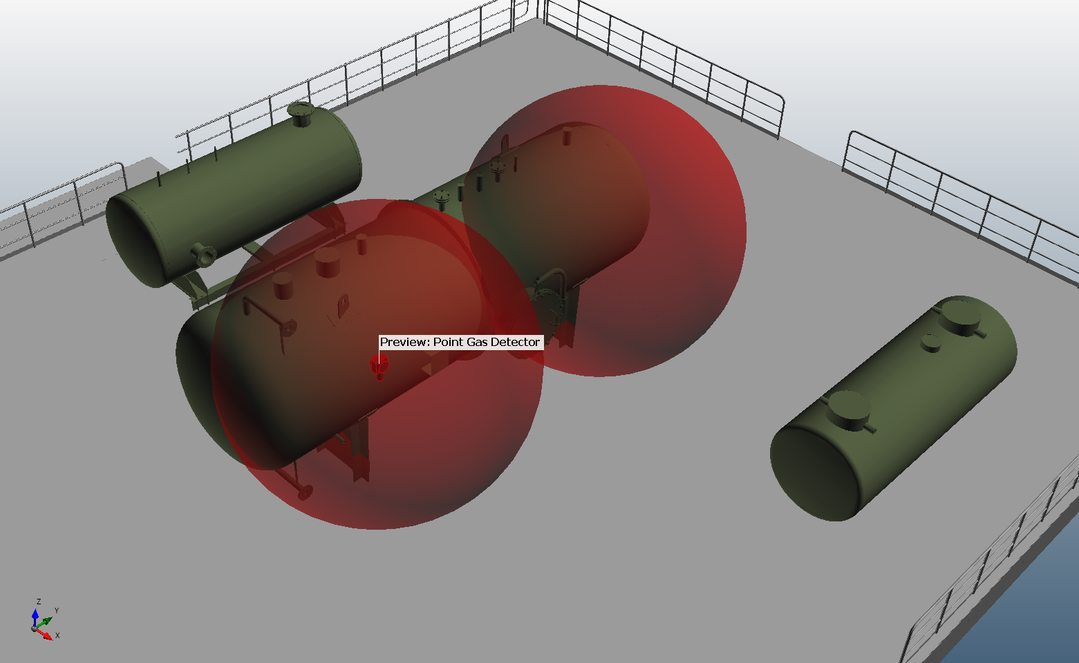
Tutorial 2 - Figure 03 - Preview of the position of the 1-dimensional array of two point gas detectors
-
Click Add Item button to add the two gas detectors to the project
-
Without returning to the Project Items tab, see that the Add Item panel remains the same and that the Name has automatically been incremented to "Point Gas Detector 03"
-
Skip down to the Location section and set the coordinates of the third detector to ( 6, 10, 3 )
-
Click Add Item to add the third gas detector to the project
Once added, three small blue models will be present in the 3D window. To view the field of influence (FOI) of the devices, right-click the Point Gas Detectors header in the Project Items Tree and select Toggle All FOIs, as shown below. This can also be done individually for each device.
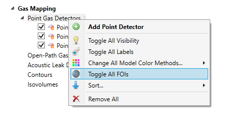
Tutorial 2 - Figure 04 - Toggling FOI Visibility for all point gas detectors in the project
The blue spheres that are now visible (seen in Figure 05) are the FOIs of the gas detectors. If the center of a hypothetical 5 m spherical LEL gas cloud was to exist anywhere within the blue spheres, the point gas detector will go into alarm. Conversely, if the center of the gas cloud was outside of the blue regions, the detector will not alarm.
In Detect3D, the default gas cloud size is set to 5 meters, you can change this value by editing the property of the risk grade for your zone. This process is described at the end of this tutorial and in Tutorial 6.
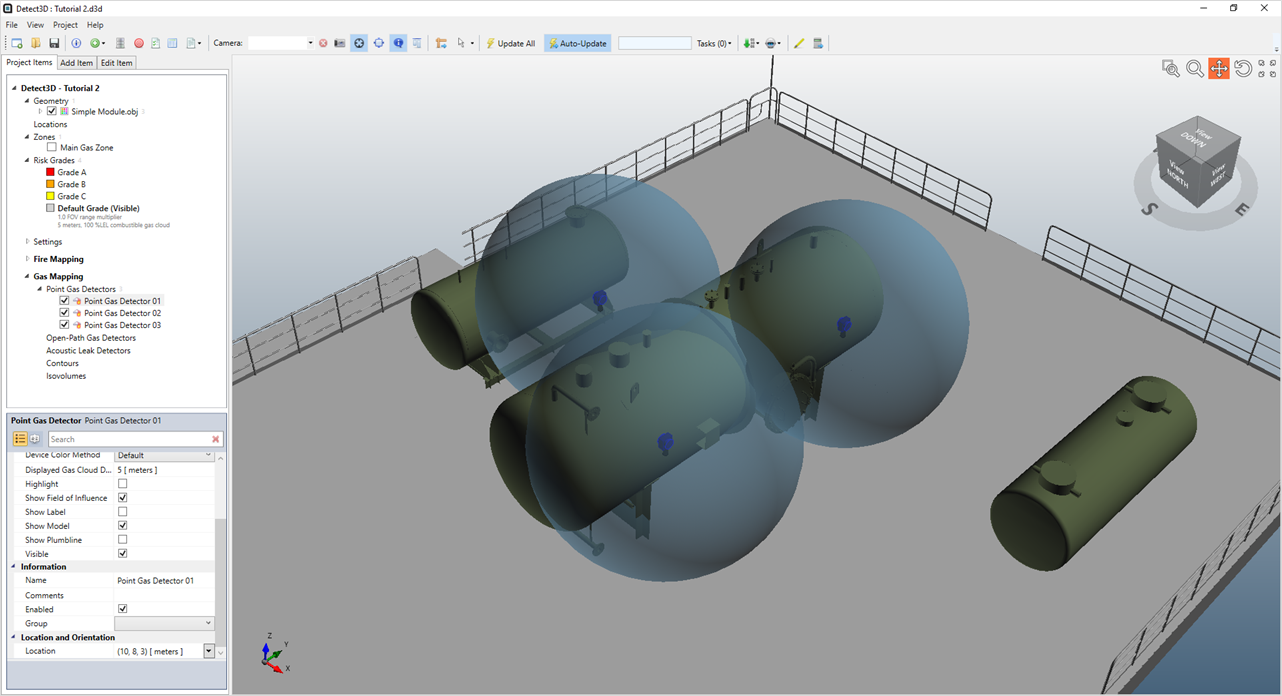
Tutorial 2 - Figure 05 - 3D window with three point gas detector's FOI visible
Before moving on to the next section, repeat the steps above to toggle off the visibility of the FOIs as it will make working in the 3D window easier. Turn on the labels for each of the gas detectors in the same way by right-clicking on the Point Gas Detectors header and selecting Toggle All Labels.