Second Sub-Zone with Equipment Pick Tool
The Equipment Pick Tool will be used to define the second sub-zone. The tool allows for specific pieces of equipment to be selected. Once selected, a shrink-wrap algorithm is applied that defines a surface around the selected equipment similar to wrapping a odd shaped gift. A radius can then be set to expand the wrap outwards from the selected equipment.
Using the equipment pick tool is easier from axis-aligned camera views (e.g. a 'top view'). For this section, change to a Top View by right-clicking anywhere in the 3D window and choosing the View From option and selecting Top View. Alternatively, you may click 'View Down' on the viewcube in the upper-right corner of the 3D window.
To add the second sub-zone to the project
-
Click the Add Item tab and select Sub-Zone from the dropdown menu.
-
Leave the Name as “Sub-Zone 02”
-
Leave the Zone as Main Zone
-
Select Grade A as the Risk Grade
-
This time, change the Type to Around Equipment
-
In the updated panel, click the Equipment Pick Tool Icon
 . The icon appears the same as the normal Pick Tool but once activated notice there are several more available keyboard commands that appear in the upper left corner of the 3D window, as seen in Figure 10. Each command is described in detail in the Pick Tools section of the help file.
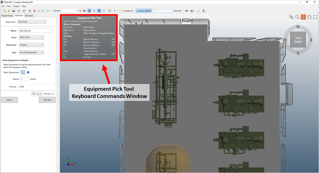
Tutorial 4 - Figure 10 - Complex Module top view with Equipment Pick Tool activated
-
The first step after activating the tool is to use the Ctrl key to make an initial selection. The best way to use this feature is to press and hold the Ctrl key and right-click once on the layer of the equipment you want to select. With the activated equipment pick tool, do this for the equipment layer as indicated in Figure 11. (using the left mouse button while holding Ctrl will select just the surface of the selected item, for the purposes of this tutorial the right mouse button should be used to copy the steps below).
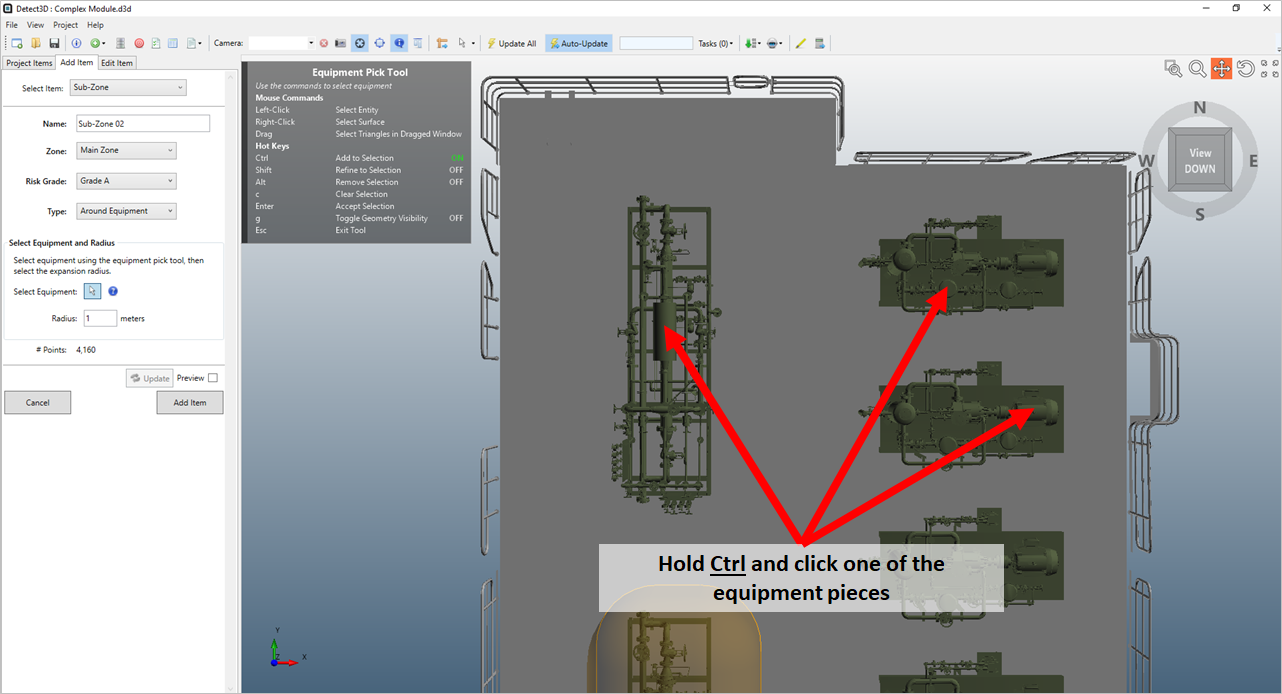
Tutorial 4 - Figure 11 - Indication of where you can use Ctrl + left click to select the equipment layer
-
After the layer has been selected, the equipment pick tool will highlight the triangles associated with that layer, as seen in Figure 12. Click the Preview checkbox and see that Detect3D has "shrink wrapped" a volume around the selected equipment (Figure 13) without the need to enter any coordinates. However, this will not be the final shape of the sub-zone for this tutorial, so deselect the preview checkbox before continuing.
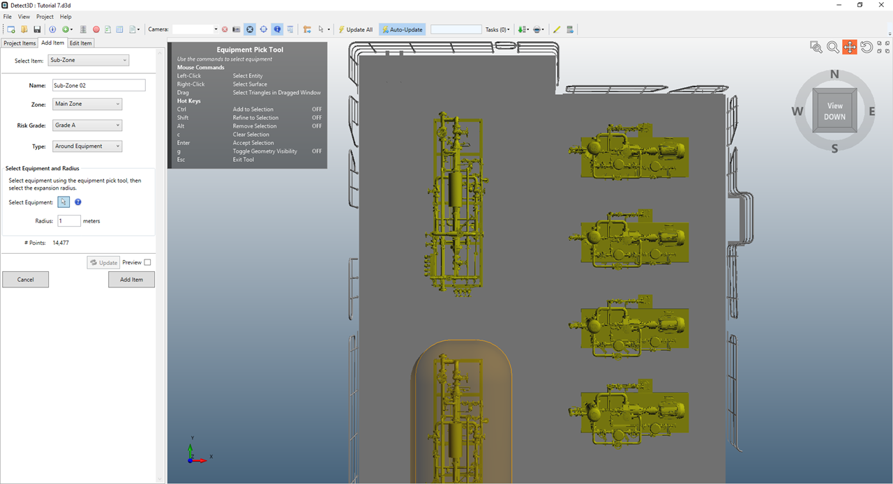
Tutorial 4 - Figure 12 - Highlighted layer after selection with the equipment pick tool

Tutorial 4 - Figure 13 - Previewed Sub-Zone 02 shrink wrapped around initially selected equipment
-
Highlighted pieces can be refined (using the Shift key) or removed (using the Alt key) to better select group or individual pieces of equipment. For Sub-Zone 02 we will select the equipment in the northwest corner of the module, at the top Figure 13. Return to a Top View and press the "g" key to toggle the geometry visibility. This will turn off the visibility of any CAD piece not highlighted.
-
Continue by holding down the Shift key and click to the upper right of the equipment shown in Figure 14 and drag a square over the equipment piece. Using the Shift key "refines" or narrows the selection of pieces highlighted. Only the pieces within the drawn square will remain highlighted after performing this step. Using the Alt key is not shown here but will remove pieces within the drawn square.

Tutorial 4 - Figure 14 - Using the Shift key to draw an axis-aligned box over the region desired to keep in the selection
-
Once the drag movement is complete and the mouse button released, only the highlighted pieces within the drawn box will be shown in the 3D window, as seen in Figure 15.

Tutorial 4 - Figure 15 - Single piece of equipment selected after using the refine capability
-
-
Click the Preview checkbox again the resulting sub-zone is now just around the single equipment piece
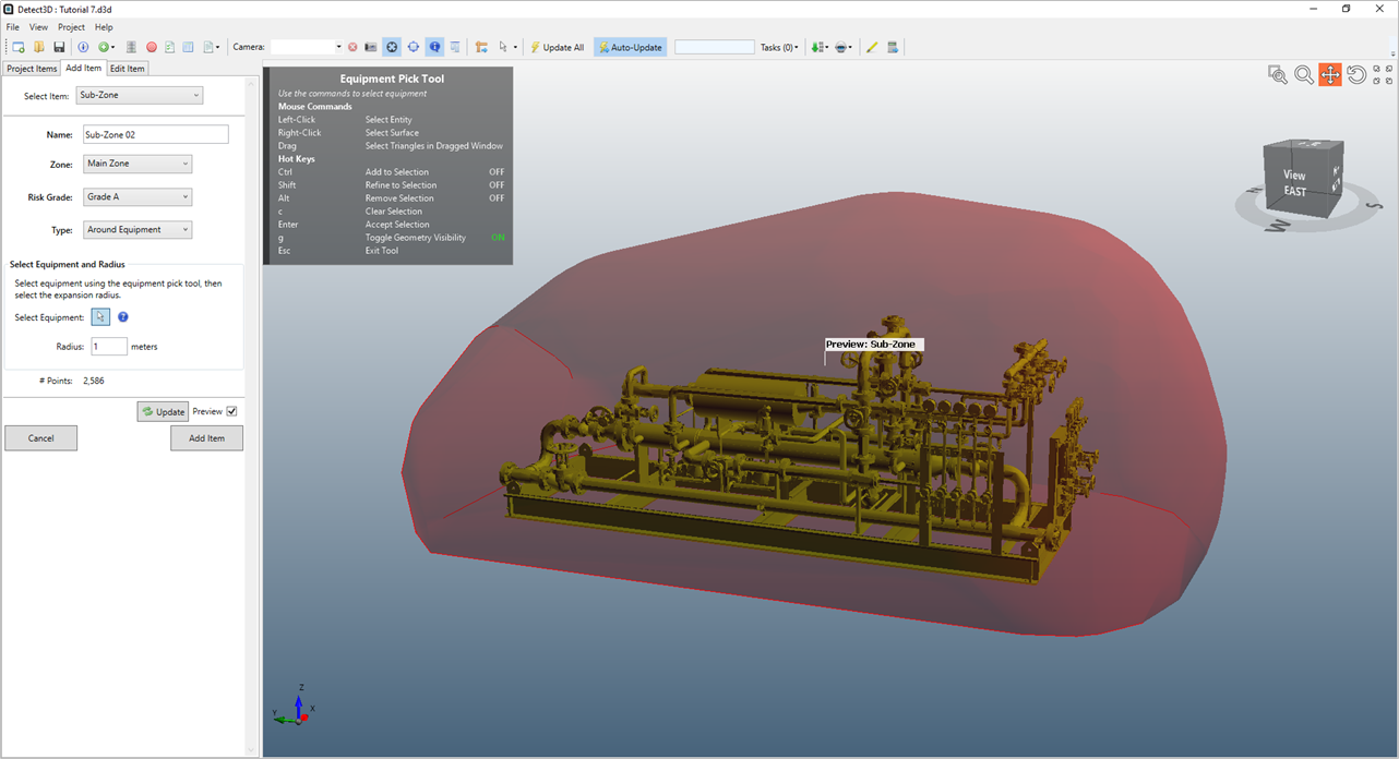
Tutorial 4 - Figure 16 - preview of "shrink wrapped" sub-zone defined 1 meter around the selected equipment
-
Leave the Radius set as "1 meter"
-
Click the Add Item button to add Sub-Zone 02 to the project. Notice that the northern edge of the sub-zone is cut-off, as seen on the left side of the sub-zone in Figure 17. This is because the edge of the main zone limits the sub-zone region. If the dimensions of the zone were edited to be larger, Detect3D would automatically extend the sub-zone region.

Tutorial 4 - Figure 17 - Sub-Zone 02 added to the project