Defining a Null-Zone
Null-Zones are volumes within a zone which are removed from the coverage calculation. They can be used to create zones which aren't a perfect square shape or to exclude equipment items or regions from being included from the coverage calculation. There is no limit to the number of null-zones that can be added, so unique zone shapes can be made. Note also that a null-zone does not remove geometry, it only affects the zone and sub-zone regions, please see this section for CAD removal features.
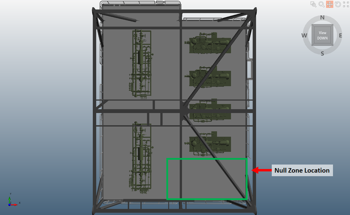
In the Complex Module.obj geometry (accessed via Help - Load Sample Geometries) used in this tutorial , there is a region with no equipment in it, indicated be the green square below. This section of the tutorial will add a null-zone to remove this volume from the coverage calculation which will significantly decrease the zero-visibility region and improve overall coverage.

Tutorial 4 - Figure 20 - Indication of unused and irrelevant space for the mapping analysis where the null-zone will be defined
To add a null zone to the project, ensure first you have defined a regular or main zone for the project. The below uses the Tutorial 4 d3d file:
-
Click the Add Item tab and select Null-Zone from the dropdown menu
-
Leave the Name set as "Null-Zone 01”
-
Set the Zone as Main Zone
-
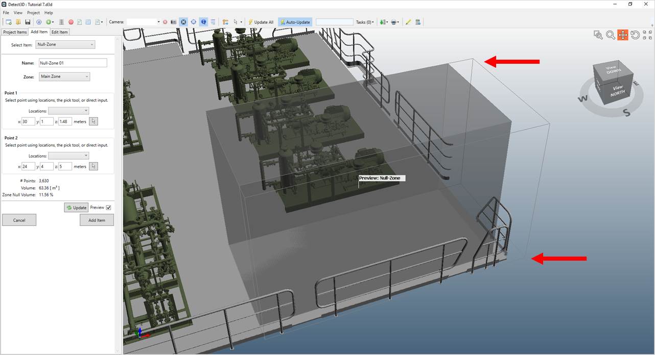
Enter ( 30, 1, 1.48 ) as the coordinates of Point 1
-
Enter ( 24, 4, 5 ) as the coordinates for Point 2
-
Click Preview checkbox and see that the extents of the null-zone extend beyond that of the Main Zone. This is indicated by the non-shaded area of the null-zone in Figure 21. This is okay to do, the volume extending beyond the zone has no effect on the coverage.

Tutorial 4 - Figure 21 - Indication of null-zone extending beyond extents of the Main Zone. The structure layer has been toggled off for this figure. The structure layer was toggled off to generate the below figure.
-
Click the Add Item button.
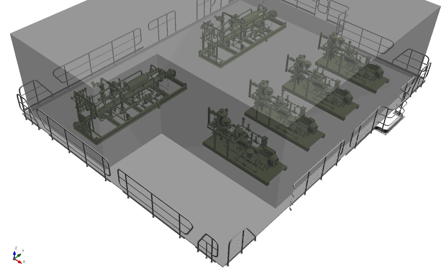
Once the Main Zone has been updated, turn on its visibility to view the updated volume where Null-Zone 01 has removed the section indicated in Figure 20 above.

Tutorial 4 - Figure 22 - View of updated Main Zone with Null-Zone 01 volume removed from the project
Continue to the next section to add detectors to the project.