Removing CAD Pieces in Existing CAD Files
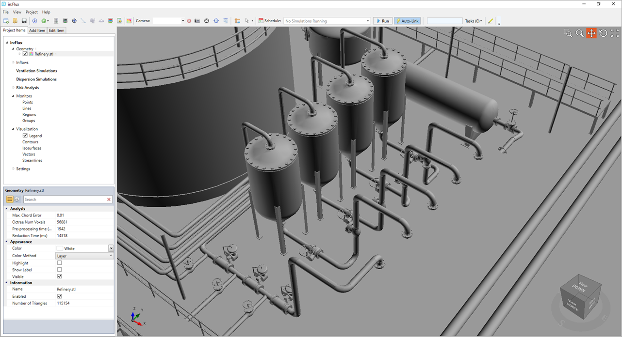
Occasionally geometry files have unwanted pieces e.g. human models, text names, superfluous equipment, etc. Both Detect3D and in:Flux comes with built in capabilities to remove individual CAD pieces as well as entire sections of CAD geometries.
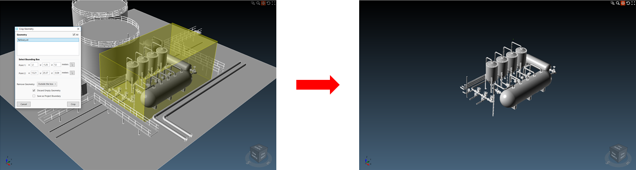
Using the Crop Tool, you may define a cuboid region to remove CAD outside or inside the defined region.
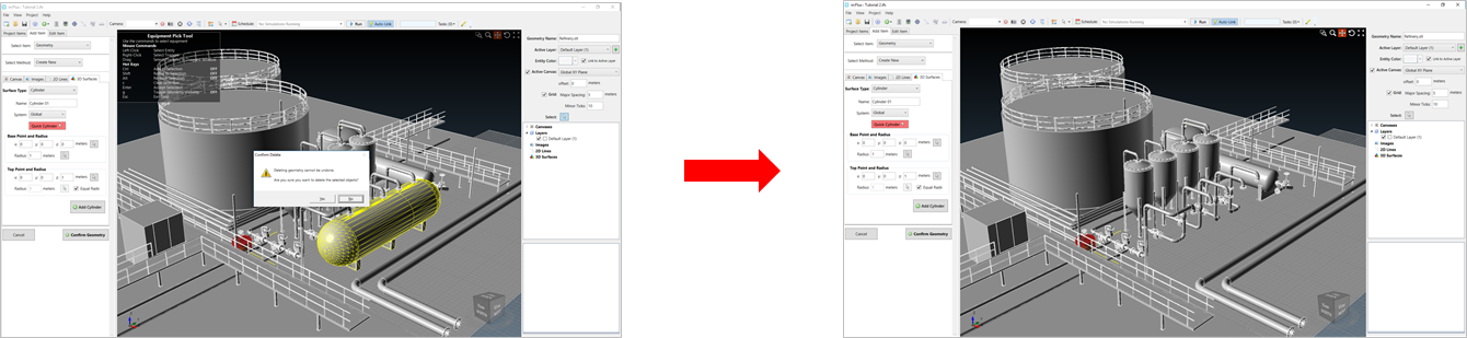
Alternatively, you may use the Equipment Pick Tool (described below) in the Create New Geometry interface to define the CAD pieces (triangles) that you desire to be removed and press Delete on your keyboard. You will be prompted to confirm that you want to remove CAD pieces before the deletion is made. It is recommended that you save your project prior.
Detailed Description of Removing Specific CAD pieces from your project:
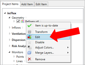
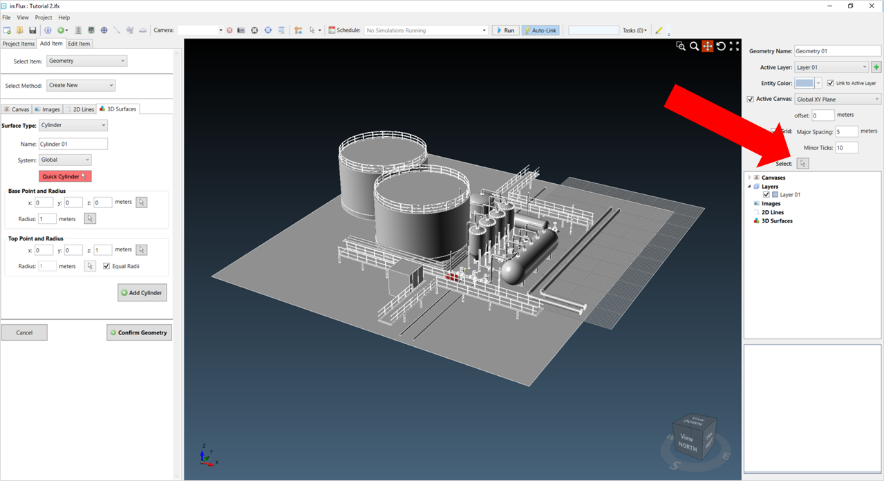
Right-click on the geometry that you want to remove entities from and select “Edit”.
You will see a new user interface, which is used for adding and editing geometry. The Equipment Pick Tool in can be used when removing CAD pieces from an imported geometry file. The symbol ![]() is the same as the pick tool icon and is located in the Geometry Creation Tool, shown below.
is the same as the pick tool icon and is located in the Geometry Creation Tool, shown below.
Once activated, the upper left corner of the viewport window will display a hotkeys list (shown below) which aide in selecting pieces of equipment.
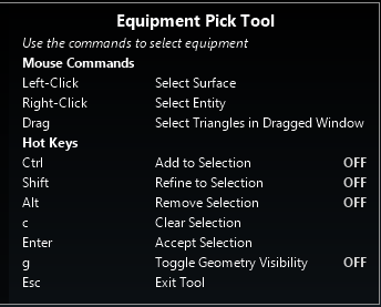
Pressing and holding the Ctrl key and using the left mouse button to click once on an equipment item will select the surface of the item selected. Using the right mouse button will select the entity or layer of the item clicked.
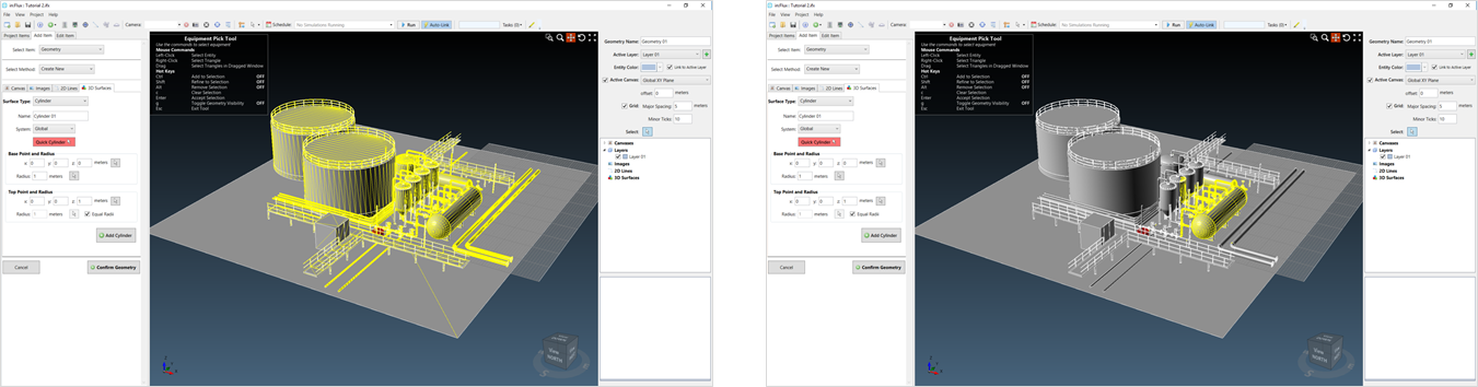
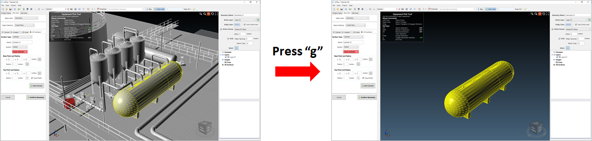
After using the ctrl key and clicking an object, the software determines all the triangles associated with that equipment item, layer or entity. If you can't see the selection, press "g" on the keyboard to toggle the visibility of the geometry.
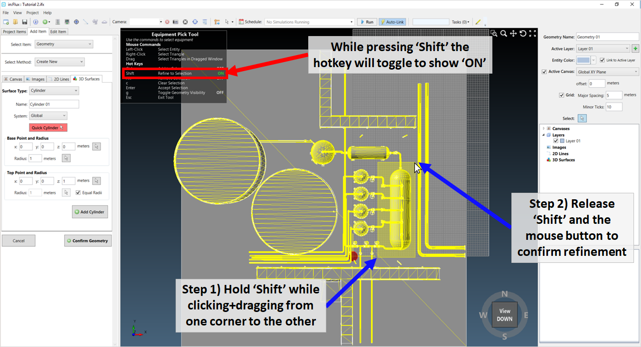
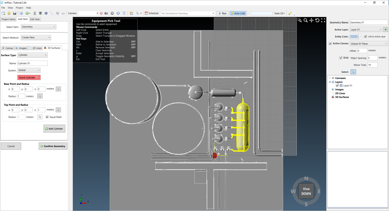
At this point you can choose to use the Shift + Drag to refine the existing selection. Everything contained in the dragged box will remain in the selection. Using this paired with different views of the 3D window significantly helps in dragging over regions of importance. Below a Top View has been used to assist in drawing the refinement region.
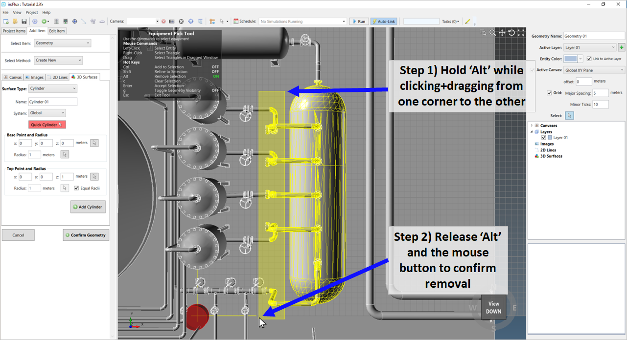
Alt + Drag will remove the dragged selection from the existing selection. As an example, in the below image, the Alt key was pressed while drawing a box over the flanges on the left side of the tank. This will remove the flanges from the selection.
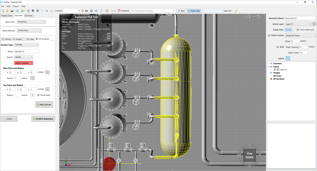
This process can be done multiple times from different view. Below the Alt+Drag method was used to remove the upper flanges from the selection by looking at a Side View of the facility.
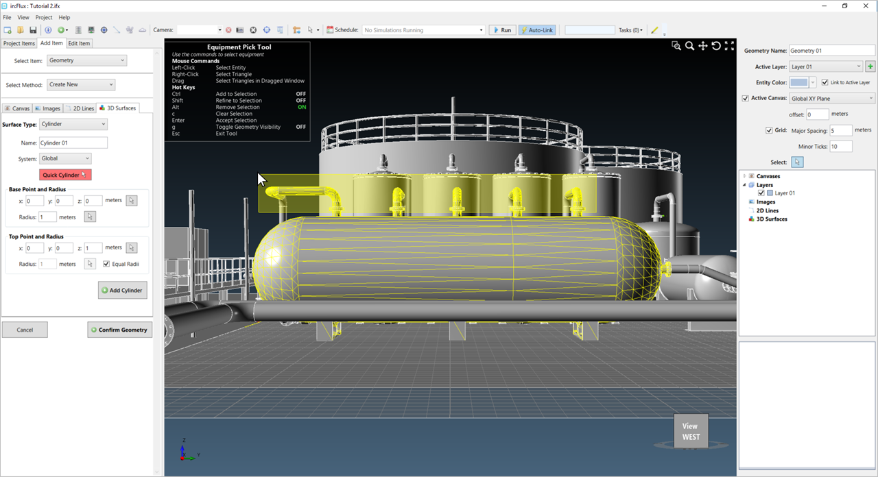
In some cases. geometry pieces are highly complex and difficult to maneuver around. To help with this difficult, or simply to verify that your selection is correct, there is a hot key for toggling geometry visibility. Pressing the "g" key, as in the example below, will visibly remove the geometry pieces which are not selected on the screen.
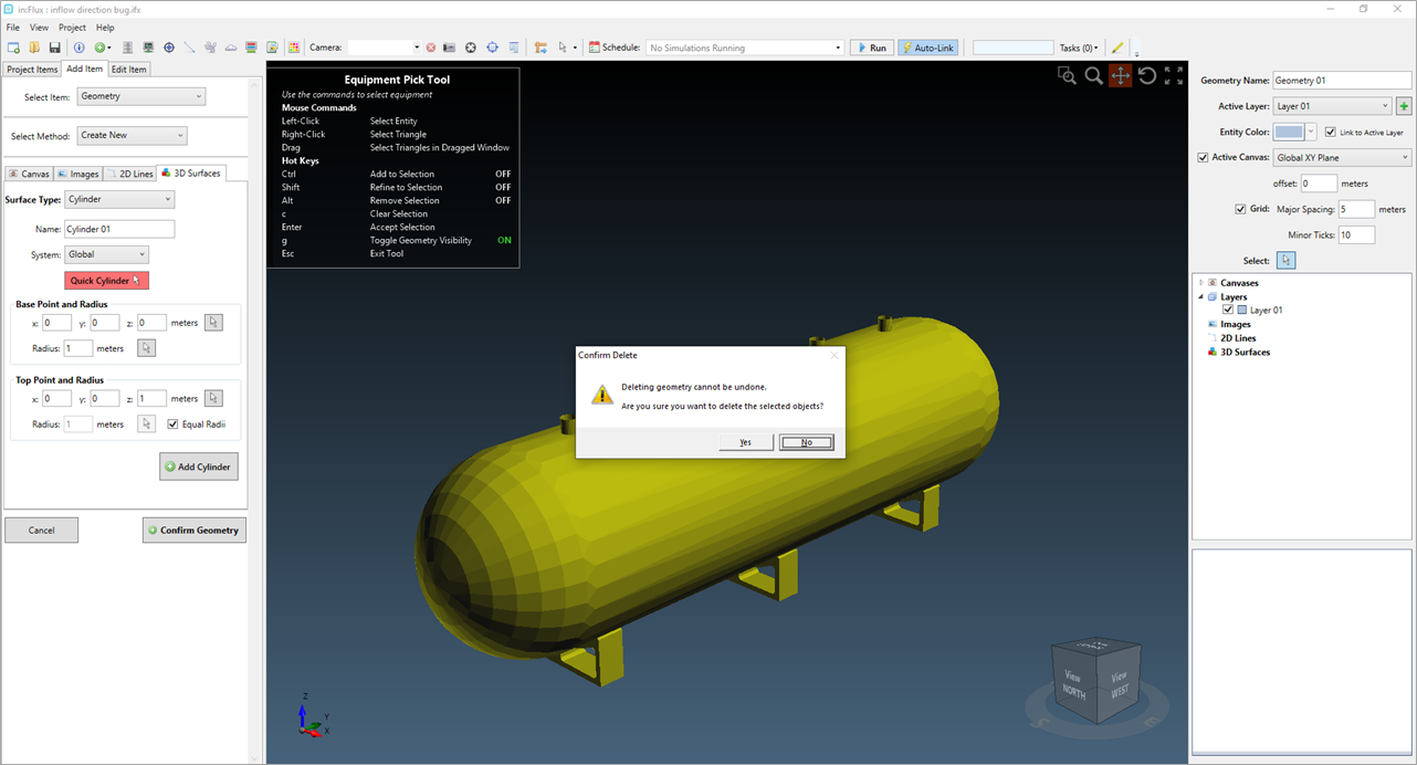
Once you are happy with the highlighted section, press the Delete key on the keyboard to remove all of the highlighted triangles from the CAD model. A warning window will appear (shown below), click Yes to confirm deletion. Be sure to save your project beforehand as this cannot be undone.
Pressing Esc will exit the Equipment Pick Tool and click Confirm Geometry at the bottom left of the screen to confirm the updated CAD model.