Adding a Streamline
A third option available for post-processing in:Flux visualizations is the streamline. Here a particle is followed from the starting edge of the flow and tracked while it is traveling through the domain. The particle is then colored as it travels to represent changing speed along its path. For in:Flux simulations, streamlines for ventilation simulations display the velocity magnitude of the particle as it traverses the domain.
To add a streamline:
-
Click the Add Item tab and select Streamlines from the dropdown menu.
-
Leave the Name to its automatically generated one.
-
Select the Westerly, 5 m/s as the Simulation.
-
Set the Seed Type to Boundary and the Direction to Forward and Backward
-
Click the Preview checkbox, your 3D window should appear similar to the figure below. Here we see an evenly distributed set of streamlines across the domain's boundary. For this project, the Boundary Seed Type does not provide us much information. We can then change the Seed Type to Line to help get a better visual for this example. Each project will be different so it is good to preview the visual prior to adding it to the project. Generally, setting a line seed type with an offset at an elevation where obstructions exist provides decent visuals.
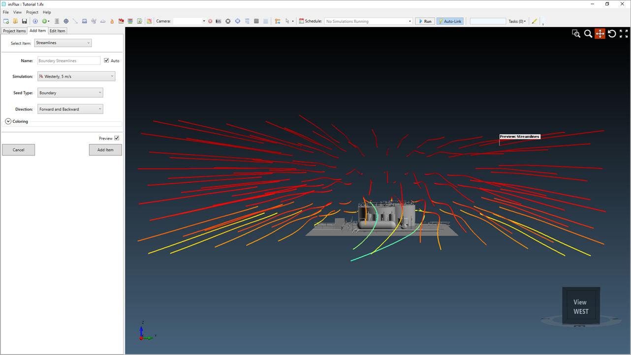
Tutorial 1 - Figure 29 - Preview of Streamline with Seed Type set to Boundary, 3D window rotated looking towards west
-
Set the Seed Type to Line.
-
Ensure that the Auto-Seed checkbox is selected and enter a value of "1.5 m" as the Offset.
-
Click the Add Item button.
Figure 30 shows the resulting streamline for the ventilation simulation. We can see how some of the flow is impacted by the large storage tanks, some particles travel under some of the railing and around the vertical tanks. The legend in Figure 30 was 'linked' to the streamlines by right-clicking the streamlines text in the project items tab and selecting Link to Legend.

Tutorial 1 - Figure 30 - Screenshot of the streamlines added to the in:Flux project for the Westerly ventilation simulation
The streamlines are truncated because they only go on for a certain period of time. The streamline will start at the seed point, then progress by a certain time step, at each point they move forward by whatever the local velocity is. To avoid the streamlines taking a long time to calculate in low velocity regions, they have to be stopped at some point. 500 is the defaulted number of time steps, this value can be changed via the properties panel and will be discussed more in Tutorial 6. Note that larger time steps will be less accurate.
The streamlines only go forward and back from the defined seed point or boundary – they are useful to give a general feel for the flow. If you are looking at the ventilation in a particular area, a contour or vector field should be used instead.