Loading Geometry
Project items can be added to in:Flux in several ways:
-
Right clicking an item in the Project Items Tab and selecting the Add button
 from the dropdown menu
 -
Clicking the Add Item button
 in the toolbar at the top of the in:Flux window
 -
Selecting the item from the Add Item Tab
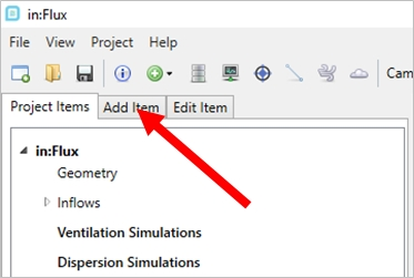
Tutorial 1 - Figure 01 - Indication of the Add Items Tab in the in:Flux UI
These tutorials will add items using the Add Item Tab pictured above.
You are not limited in the number of CAD files which can be imported nor the complexity/size of the file. These files can be Microstation (.DGN), DWF (for Navisworks import), AutoCAD DWG, DXF or other standard CAD formats (STEP, IGES, OBJ and STL). If you have already imported a CAD geometry into an in:Flux or Detect3D project, you may choose to import the CAD data from the .d3d or .ifx project file rather than load the raw CAD file again.
To import a geometry:
-
Click the Add Item Tab and choose Geometry from the Selected Item dropdown menu.
-
Ensure that the Import 3D CAD File option is selected from the Select Method option.
-
Click the Browse To File.
-
Navigate to the in:Flux tutorials directory (usually C:\Program Files\inFlux\Tutorials), select Refinery.stl and click Open. You can also find this, and other sample geometries under the help menu which are pre-installed with in:Flux.
-
A small window will appear (shown below) which displays the bounding dimensions and units to import the selected geometry into. A section called Triangle Reduction is listed in the middle of the window, leave this as the defaulted option Medium (10mm). Make sure that meters is selected from the Select Units option at the top and click Confirm. Please see the CAD Geometry section of this documentation for how geometry is represented in in:Flux.
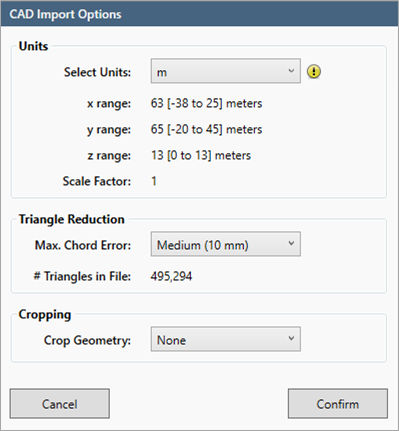
Tutorial 1 - Figure 02 - CAD Import Options window
The loaded geometry should appear as the figure below. Take some time at this point to test out each of the viewing buttons in the top right of 3D window.
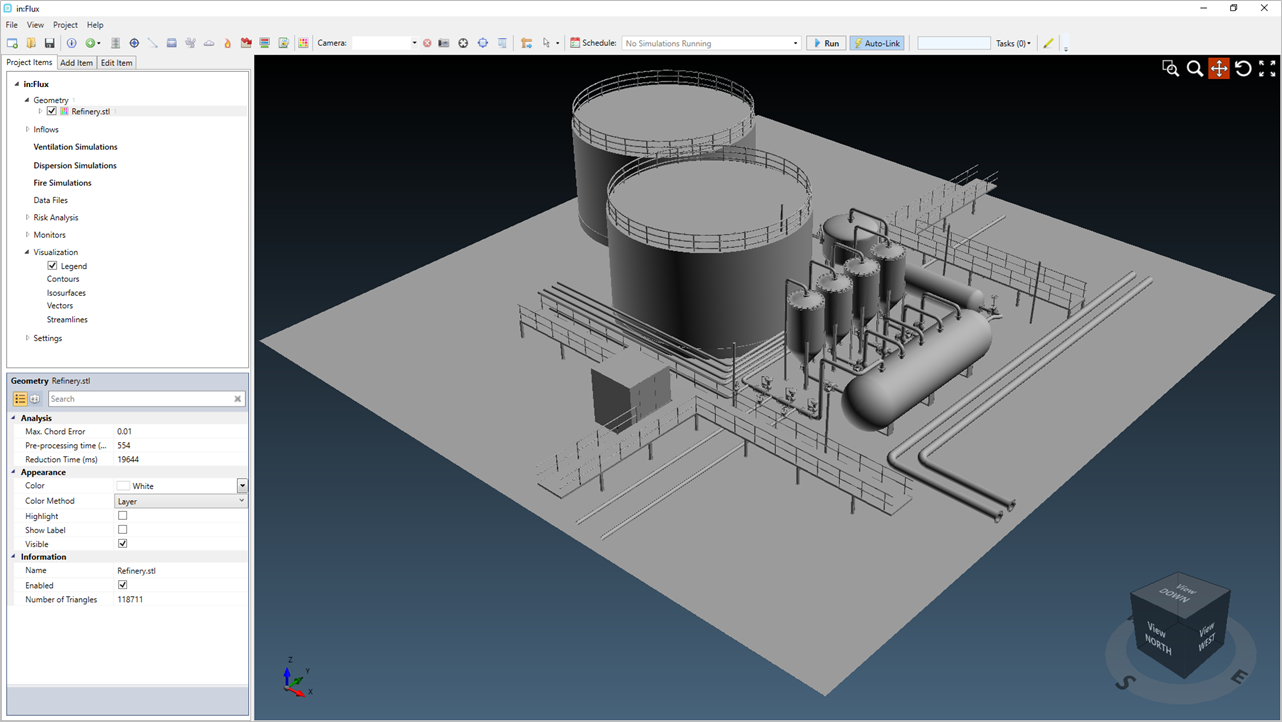
Tutorial 1 - Figure 03 - in:Flux window after loading the Refinery.stl CAD file.
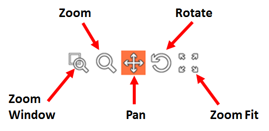
Tutorial 1 - Figure 04 - Viewing buttons at the top right of the 3D window, whichever item is selected (in red) is the function the left mouse button will perform when clicked
Maneuver around the CAD model and zoom into different parts of the geometry to get accustomed to the controls. Each mouse button can be utilized within the 3D window:
-
The left mouse button is defaulted to pan
-
The middle mouse button (when held) will rotate, and scrolling will zoom in and out
-
The right mouse button will open the View menu and allow for selection of varying viewing angles
When you are comfortable with traversing around the 3D window continue onto the next section.