Post-Processing Results for Custom Gas Emission
When the dispersions have complete, contours and isosurfaces can be defined to view the results.
For this tutorial a vertical contour will be defined as well as three isosurfaces at various concentrations.
To define the vertical contour:
-
Choose Contour as the Select Item from the Project Items Tab
-
Ensure that Exhaust Inlet on Easterly, 5m/s is selected as the Simulation
-
Set the Variable to Exhaust Volume Fraction, %vol
-
Change the On Plane option to ZX Plane, with an Offset at Y= -0.5m
-
To add some interesting coloring, expand the Coloring panel and set the Palette to Magma and click the Reversed checkbox.
-
Lastly, lower the Opacity slider so that the contour is slightly transparent.
-
Click the preview checkbox, your screen should be similar to the figure below.
-
Click the Add Item Button to add the contour to the project.
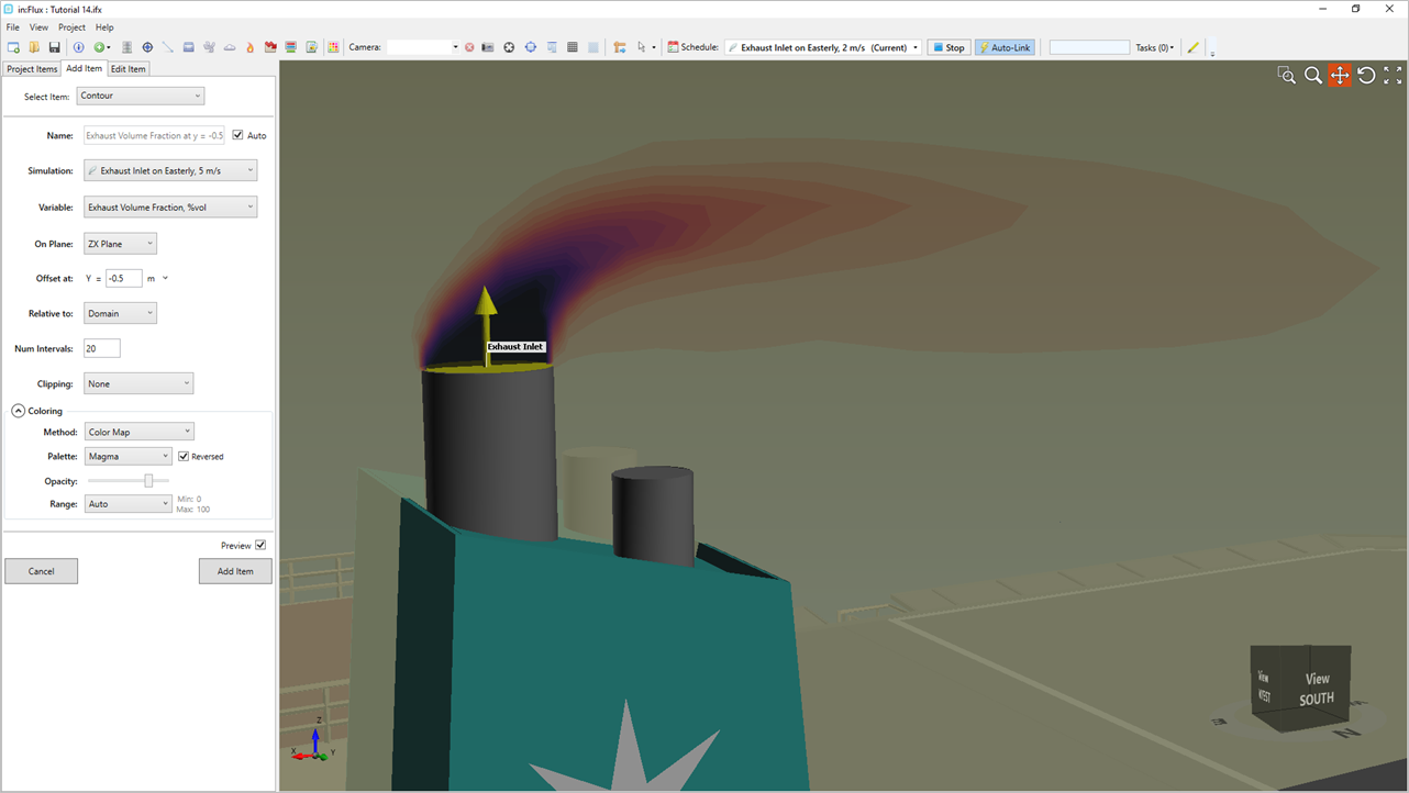
Tutorial 14 - Figure 10 - Preview of Exhaust Volume Fraction Contour with reversed Magma Color Palette
Toggle off the visibility of the contour and return to the Add Item Tab to define the isosurfaces.
-
Select Isosurface from the Select Item dropdown
-
Set the Simulation to Exhaust Inlet on Easterly, 5m/s
-
Use the same Exhaust Volume Fraction, %vol variable as above and enter "10%" as the Value
-
Set the Color as Red and click the Add Item Button.
-
Repeat Steps 3 and 4 above to add a second isosurface at 1% volume, changing the color to orange and increasing the opacity before adding a third isosurface at 0.1% volume with a lower opacity value and a different color, such as blue. See Step 9 from this section to edit the transparency of isosurfaces.
You should now have three isosurfaces defined resembling the figure below. Note that isosurfaces can show non-integer values of concentrations, values down to 0.0001% may be needed for some projects.
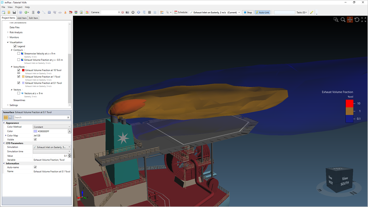
Tutorial 14 - Figure 11 - Three isosurfaces for 10%, 1% and 0.1% volume fractions of the defined exhaust on the Easterly, 5m/s wind
The isosurfaces can be switched to link with the Easterly, 2m/s case as well. Notice how the plume is large with the lower wind speed.
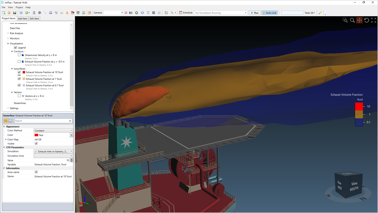
Tutorial 14 - Figure 12 - Three isosurfaces for 10%, 1% and 0.1% volume fractions of the defined exhaust on the Easterly, 2m/s wind
Results of percent volume of the exhaust can also be viewed in monitor points placed around the domain as shown below.

Tutorial 14 - Figure 13 - Series of Monitor Points showing percent volume of each case in the Monitor Point Data Window
This completes Tutorial 14. You should now understand how to setup and run custom gas emissions.
If you have any questions regarding the setup conditions for your project please contact us at info@insightnumerics.com