Loading a File and Inflow Setup
To start, open the Tutorial 1.ifx save file. Alternatively, you may load the Refinery.stl file from the in:Flux tutorials directory and run a Westerly, 5m/s wind case. Turn off all post-processing visualizations before continuing below.
Inflows, or leaks, can be pointed in any direction regardless of the wind or geometry axis. The sizes of inflows can be defined in terms of diameter (used in previous tutorials), flow rate or power (used in this tutorial). The same inflow from Tutorial 2 can be used here but for demonstration purposes another leak is being defined.
As of v2.0 of in:Flux the fire simulations are only single-step hydrocarbon reactions, multi-component gases can be used and can contain non-hydrocarbon components. Additionally, only one reaction per simulation is allowed, meaning inflow groups cannot be used.
Setup the leak as follows:
-
Click the Add Item tab and select Gas Leak or Emission from the dropdown menu.
-
Set the Type as High Pressure Gas Leak and set the Name to "Pure Methane 100MW"
-
Set the Gas to METHANE from the dropdown menu. You may opt to define a multi-component gas here but for this tutorial only a single-component pure gas is used.
-
Set the Upstream Pressure to "20 bar(g)" and the Temperature to "30°C".
-
Leave the Discharge Coefficient as "0.8"
-
Mouse over the Diameter text and select Power from the available options, as shown in the image below. Set the units to MW and enter "100" as the value. Once a value is entered, you can switch between the diameter and flow rate options to see the equivalent values. Return the option to Power and continue to the next step.
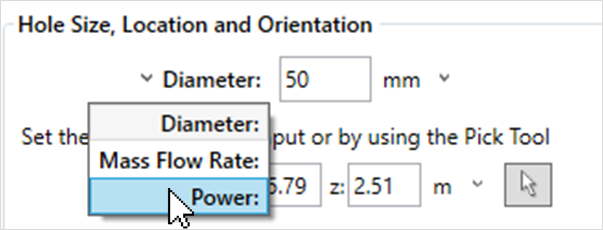
Tutorial 15 - Figure 01 - Selecting the size of inflow based on the entered power rather than diameter.
-
For the Location, enter the following coordinates ( -6.57, 22.96, 5.93 ), or use the pick tool
 to select the north side of the valve as in Figure 02 below.
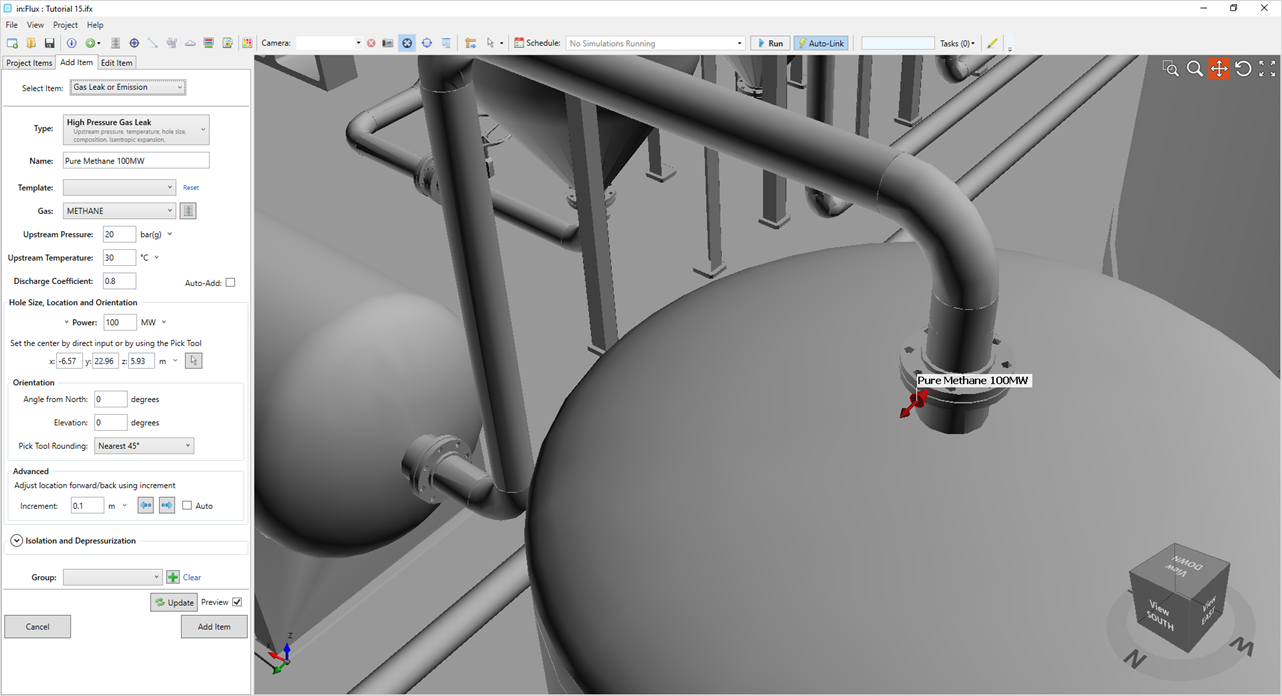
Tutorial 15 - Figure 02 - Location of inflow for jet fire simulation
-
If you entered the coordinate, set the Angle from North set as "0" and Elevation as "0". If you used the pick tool, ensure these values are the same as the automatically selected ones.
-
Leave the other options as is and click the Add Item button.
The added inflow will appear as a green arrow as shown below. Proceed to the next section for setting up and running the jet fire simulation
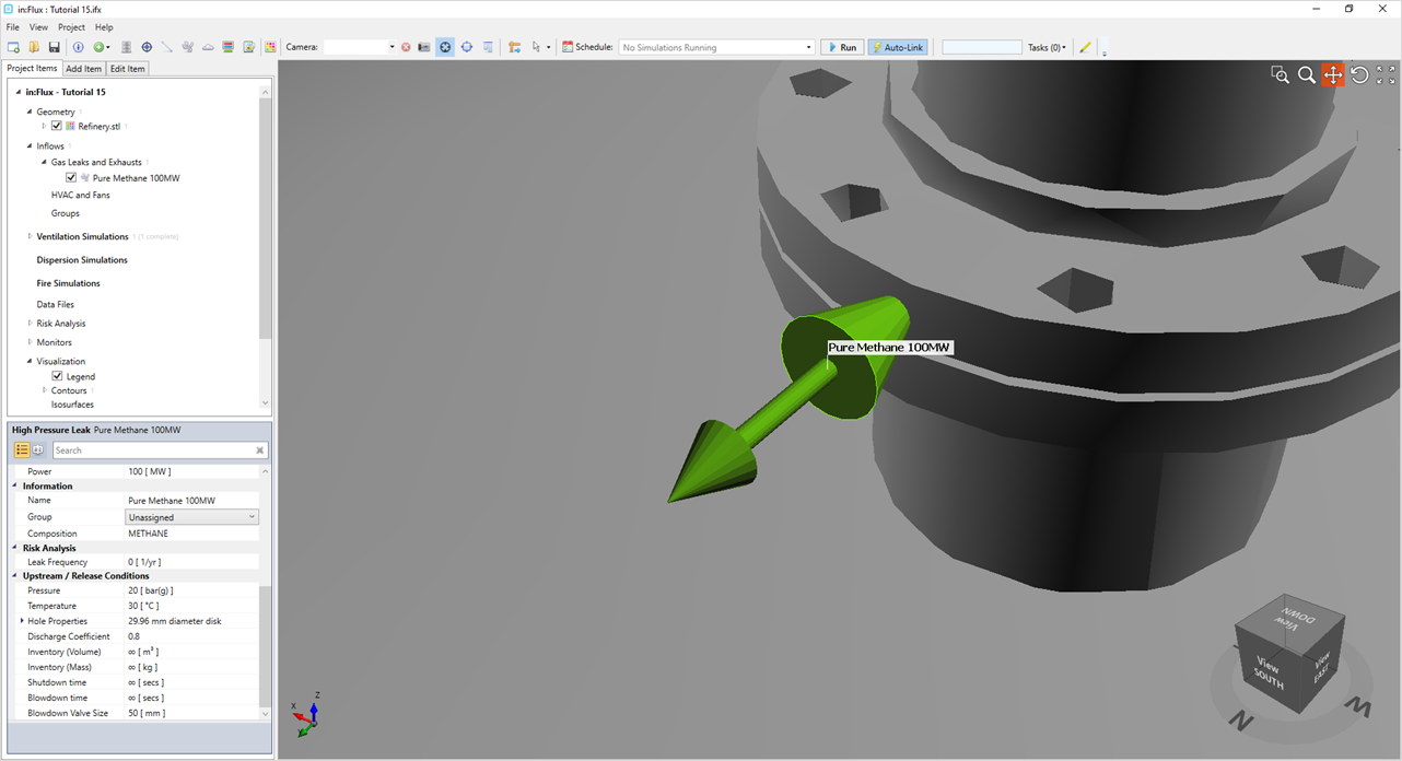
Tutorial 15 - Figure 03 - Addition of Pure Methane 100MW inflow to the Project