Defining a Pool Fire - Disc Shape
Open the Tutorial 15.ifx project file and save as a new file "Tutorial 18.ifx" This will retain the existing CAD, ventilation and monitor points. For this tutorial a single-component Heptane inflow will be defined but you can also use multi-component liquids defined in the same way as Tutorial 7: Multi-Component Gases..
From the Add Items Tab select, Gas Leak or Emission as the Select Item and continue the steps below:
-
Set the Type as Evaporating Pool
-
Change the Name to Pool Fire Inflow - Disc Base
-
Set the Gas to Heptane or you may choose from the available options in the DIPPR® Liquids Database by clicking the
 icon
icon -
Leave the Evaporation as Automatic (Pool Fire) and in:Flux will calculate the appropriate evaporation rate based on the liquid, temperature and size of pool defined. Note: this feature is only available for fire simulations and will not be applicable for dispersion or custom gas emission simulations.
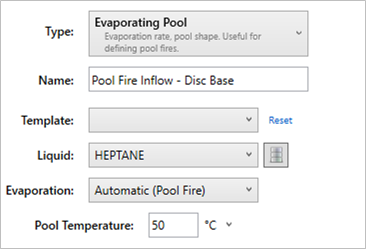
Tutorial 18 - Figure 01 - Initial inputs for evaporating pool fire case
-
Alternatively, you may change the Evaporation option to User-Defined, and enter a mass flow rate, mass flux, or regression rate as shown below but doing this will product different results than shown in this tutorial.
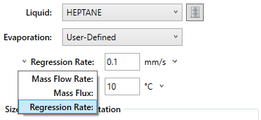
Tutorial 18 - Figure 02 - Changing input variable for an evaporating pool to a user-defined option rather than the automatically calculated one
-
-
Set the Pool Temperature to "50°C"
-
For the Selection, choose Circle and set the Method to Center and Diameter. As its name suggests, using this option lets us specify a diameter of the disc and the location.
-
Enter the Diameter to be "1 meter"
-
For the location, use the pick tool to select a point under the southern most vertical tank as shown in Figure 02 below, or enter the following coordinates ( 1.3, 5.5, 0 ). This location was chosen to represent the flanges leaking and the formed pool catching fire. We will also be able to see the affect of the vertical tank and the wind on the developed plume.
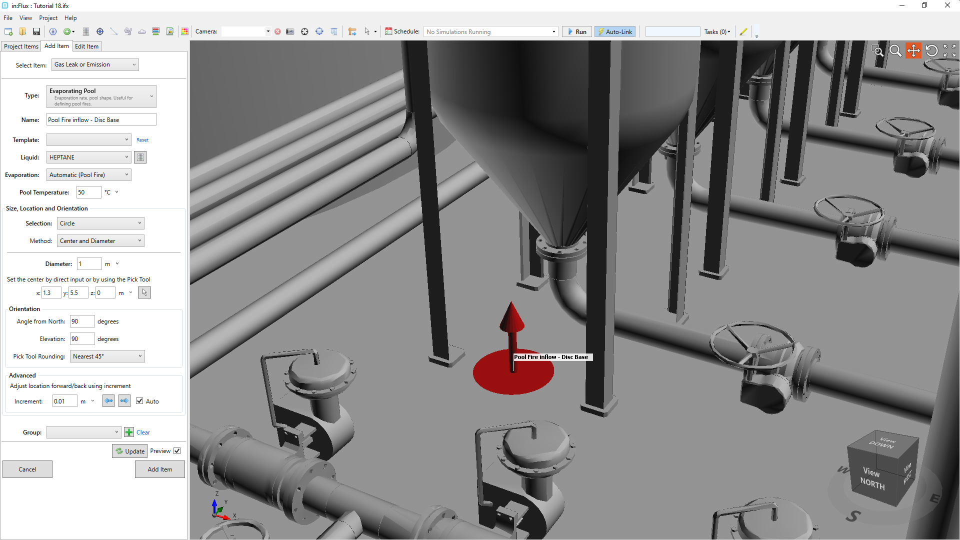
Tutorial 18 - Figure 03 - Location and input parameters for Pool Fire Inflow - Disc Base
-
Because the inflow is located on the ground, the Angle from North can be ignored but ensure that Elevation is set to "90 degrees"
-
Click the preview checkbox, if you cannot see a red disc as in Figure 02 above, then the point selected with the pick tool may be positioned lower than the ground level. If this is the case for you, click once on the forward button (
 ) to increment the inflow location forward by 0.1m.
 -
Confirm that your screen is similar to Figure 03 above, click the Add Item button.
Continue to the next section to add a second pool fire inflow to the project.