Adding Porous Regions for Grated Decks
Most decks in offshore projects are grated, however some CAD models only show these decks as plated. It is good practice to always double check with the project documents to verify which decks are plated and which are grated, as the latter allows wind and gas to pass through it and will affect ventilation and dispersion results.
This section will go over how to define two porous regions to represent a grated deck.
Open the Offshore Rig - CAD Only.ifx file and save it as a new project.
-
Choose Porous Region as the Select Item from the Add Items Tab
-
Zoom into the upper deck region indicated by the figure below. For this tutorial, the analysis is focused on the region indicated and have the upper most deck with process equipment modeled as grated. The other decks will be left as plated for brevity.
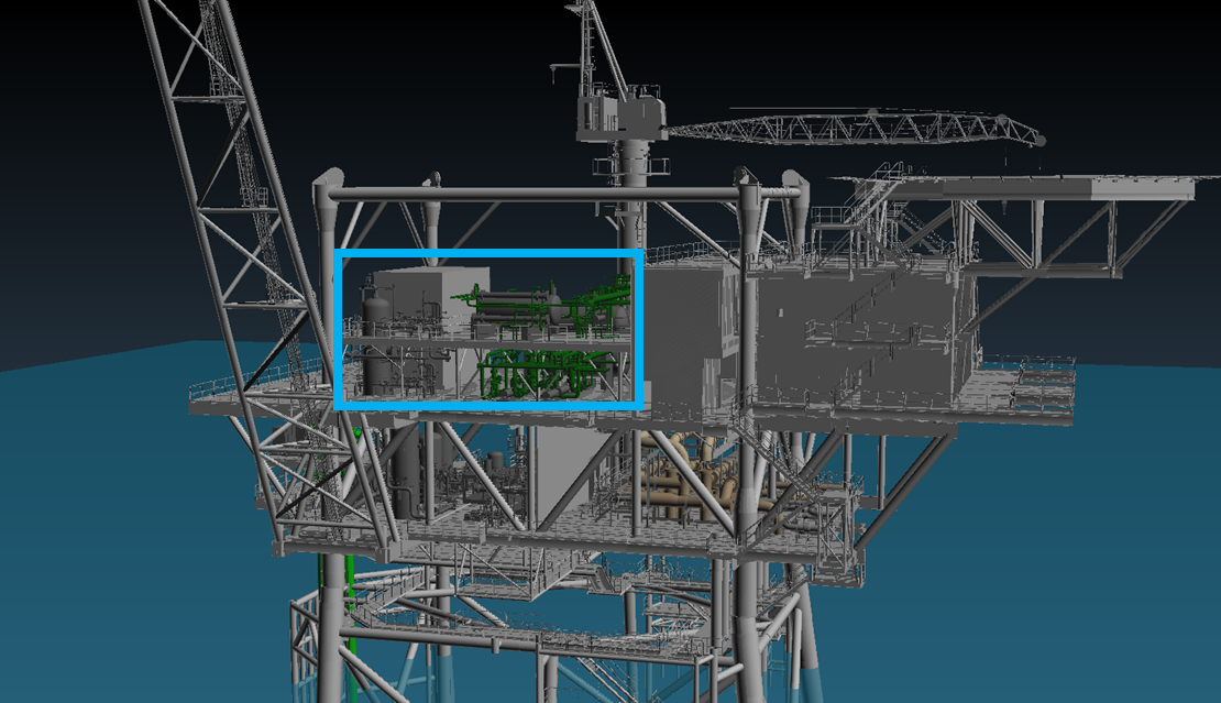
Tutorial 19 - Figure 1 - Location for grated decks to be defined
-
Using the measure tool (
 ) to estimate the height of the deck. This will be used as reference for one of the z-coordinates of the porous region. The figure below shows the deck height
as 25.12m so the upper z-coordinate of the porous region should be slightly above this value to ensure it encompasses the deck. Repeat the same process for checking the underside of the deck and you should find the height of the underside of the
deck to be 25.1m thus the other porous region definition point should be lower than this value.
) to estimate the height of the deck. This will be used as reference for one of the z-coordinates of the porous region. The figure below shows the deck height
as 25.12m so the upper z-coordinate of the porous region should be slightly above this value to ensure it encompasses the deck. Repeat the same process for checking the underside of the deck and you should find the height of the underside of the
deck to be 25.1m thus the other porous region definition point should be lower than this value.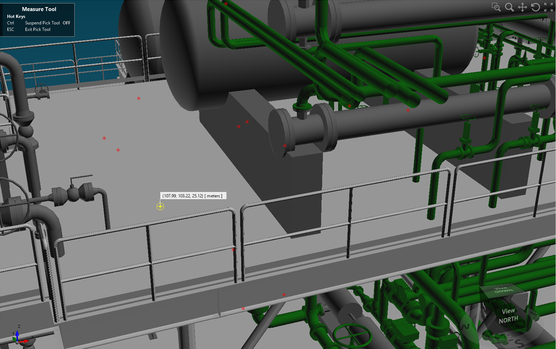
Tutorial 19 - Figure 2 - measuring height of deck to determine z-coordinates of encompassing porous region
-
Use the two pick tools to select opposing corners of the deck as indicated below, or enter the following coordinates: Point 1 (105.95, 109.35, 25.15 ) and Point 2 as ( 120.98, 101.16, 25.09 ). Note the values for each of the z-coordinates - the first is entered to be slightly above the measured upper bound of the deck height found in Figure 2 and the second point is slightly lower than the measured upper bound mentioned in Step 3.
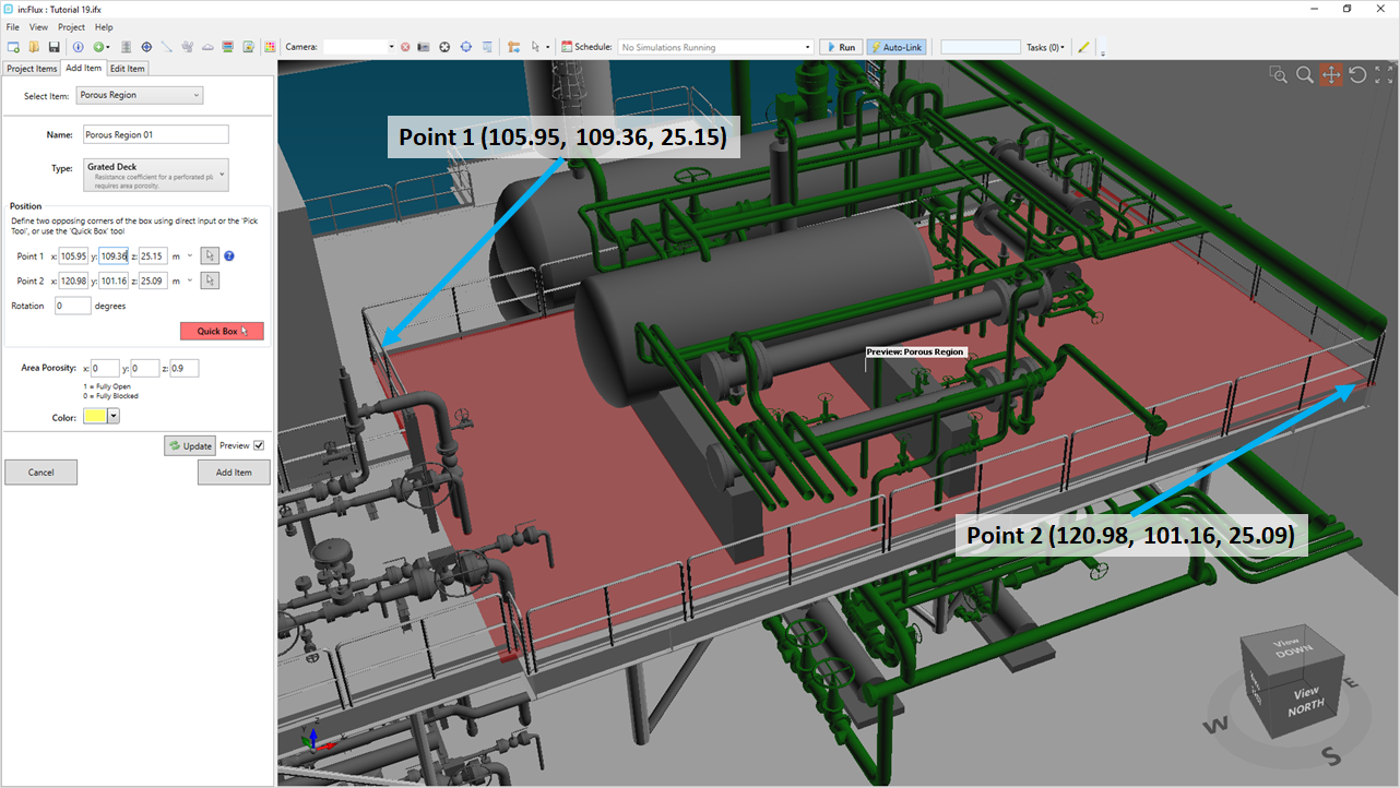
Tutorial 19 - Figure 3 - Definition Points for Porous Region 01
-
As this is a porous region replacing a grated deck, it will use an area based porosity, meaning flow is only allowed to travel in one direction through it - set the Z Value to "0.9" meaning 90% of the flow will be allowed to pass through the region in the z-direction. This value is generally accepted as the percentage of flow to pass through grated decks when performing CFD analysis.
-
Click Add Item
-
Because this deck is not a perfect square shape and has two sections, another porous region will be defined. Stay in the same panel and enter the following coordinates for Porous Region 02 - Point 1 as ( 102.9, 106.19, 25.15 ) and Point 2 as ( 105.95, 101.16, 25.09 ). Note for this region the x-coordinate is made to match that of the western edge of the first porous region. Additionally both z-coordinate values are left the same.
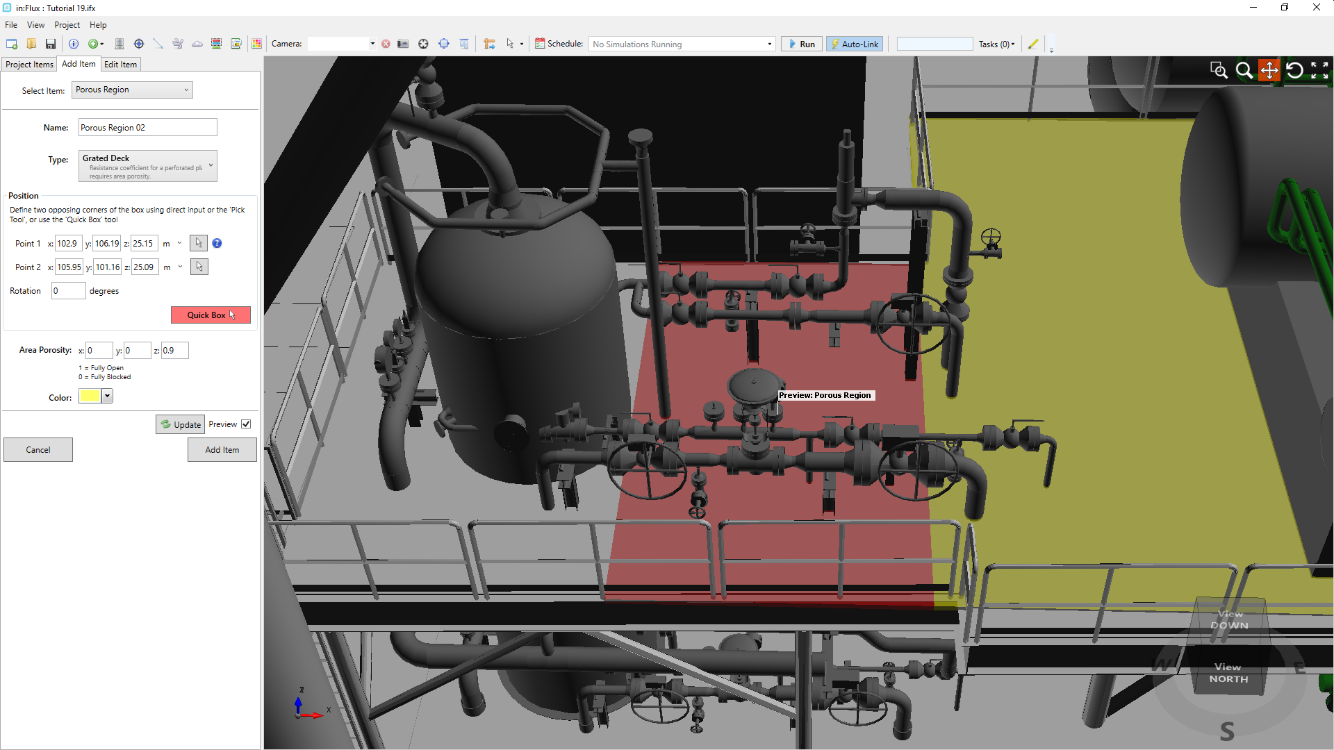
Tutorial 19 - Figure 4 - Definition of Porous Region 02
-
Ensure that the Z Value for the Area Porosity is "0.9" and click Add Item.
Notice how Porous Region 02 was defined to not include the vertical tank in this example. It is important that porous regions defined in this way not cut through large tanks or other equipment. If the porous region were defined dividing a tank then flow would be allowed to travel inside the tank which is not desired. For the purposes of this tutorial only two porous regions have been defined around the upper deck and vertical tank on the west side. The rest of the geometry is left as plated decks as the leaks defined in the next section will only be within the area indicated in Figure 1.
Continue to the next section to setup leaks for the fire simulations.