Defining Monitor Surfaces
Open the Tutorial 16.ifx file which already has 5 completed fire simulations ranging in size.
For this example, four monitor surfaces will be added to the project to review surface heat flux information for each of the completed simulations. There is no limit to the number of monitor surfaces that can be defined in a single project.
To add the first monitor surface to the project, select Monitor Surface from the Add Items Tab:
-
Enter a Name as "Vessel 01"
-
Set the Emissivity to User Defined and enter a value as "0.8" or choose from the available list of material emissivity values by opening the dropdown menu shown below
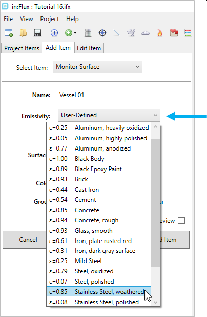
Tutorial 20 - Figure 00 - Emissivity dropdown menu showing available options for various materials
-
Use the Equipment Pick Tool to select the vessel shown in Figure 01 below. this can be done by activating the pick tool and while holding the Ctrl key, clicking once on the vessel. Doing this will highlight the equipment item in yellow.
-
Confirm your selection is similar to the figure below and press the Enter or Return key on the keyboard to accept the selection.
-
Leave the Color and Group options as-is and click Add Item
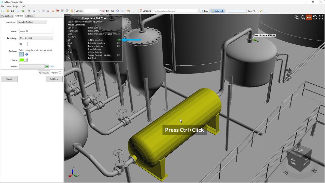
Tutorial 20 - Figure 01 - Using the equipment pick tool to select a single vessel to define a monitor surface
Repeat the above steps to add a second monitor surface with a Name of "Vessel 02" and same Emissivity for the large horizontal vessel on the eastern side of the model, shown below.
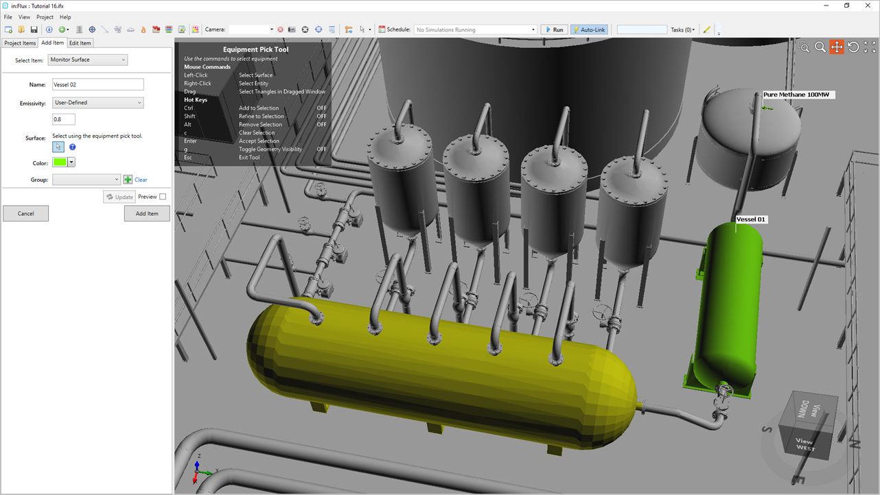
Tutorial 20 - Figure 02 - Definition of second monitor surface using the equipment pick tool on a second horizontal vessel
The equipment pick tool can be used to create a single monitor surface from multiple equipment items:
-
Create a third monitor surface with the Name "Vertical Vessels"
-
Enter an Emissivity value of "0.8"
-
With the Equipment Pick Tool press and hold the Ctrl key and click once on each of the four vertical vessels so that your screen matches Figure 03 below.
-
Hit the Enter or Return key on your keyboard to confirm the selection
-
Click the Add Item button.
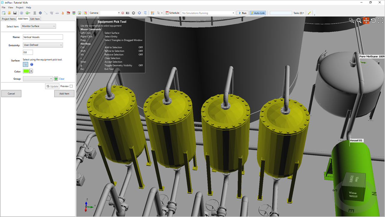
Tutorial 20 - Figure 03 - Selection of four vertical vessels as one monitor surface
Now these four vertical tanks will be considered as one surface item when calculating the average and maximum heating and temperature values.
Lastly, define two more monitor surfaces - one for each of the large tanks located on the western side of the model, the below example gives a Name of "Tank 01" as the tank closer to the leak location and "Tank 02" as the tank furthest west.
Once complete you should have five monitor surfaces defined, turning on each's visibility and labels will produce a screen similar to the figure below.
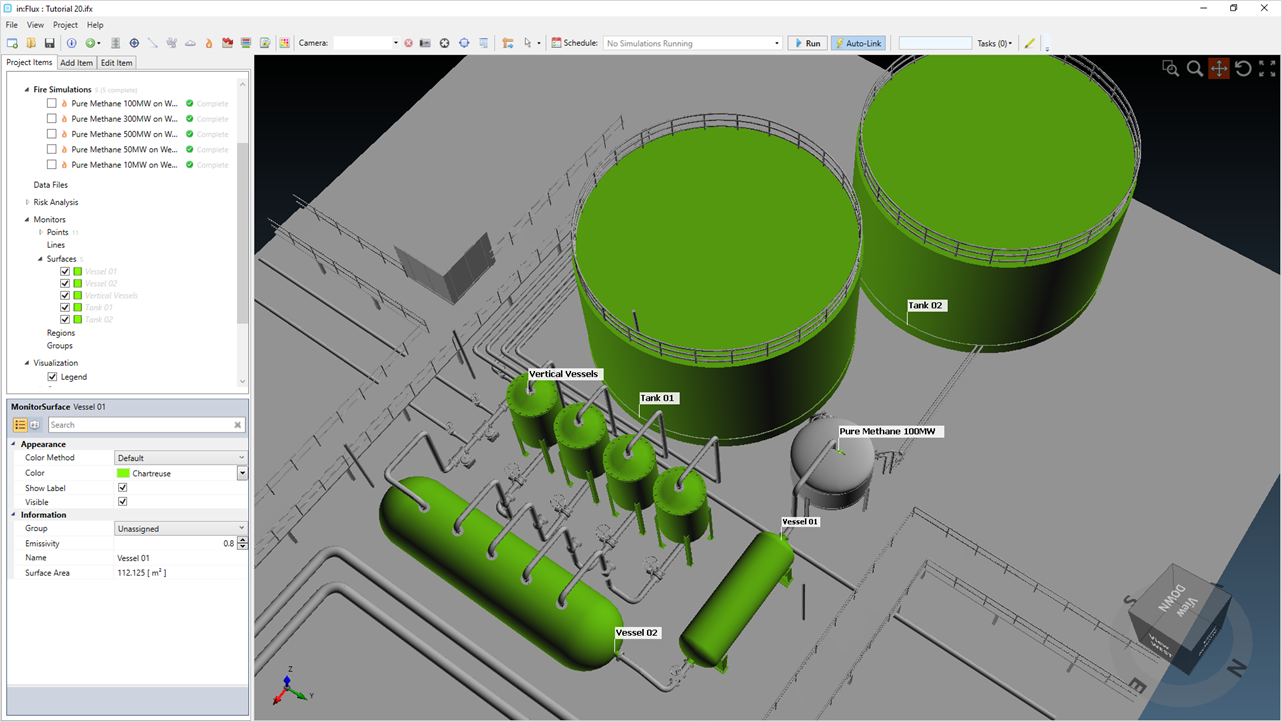
Tutorial 20 - Figure 04 - in:Flux window showing five monitor surfaces defined in the project
Each of the monitor surfaces will have grey text in the Project Items Tab. Continue to the next section to update the monitor data and review the results.