Flattening Isosurfaces onto a Plane
A 3D isosurface shows the envelope of a variable at a chosen value - for example, the surface bounding the region where gas concentration exceeds the lower flammable limit, or where incident radiation exceeds a thermal threshold. While the 3D form is informative, deliverables for engineering review and reports are often easier to interpret as a 2D projection. The "flatten" option, added in version 4.0, collapses an isosurface onto a chosen plane to produce a maximum-extent projection in a single direction.
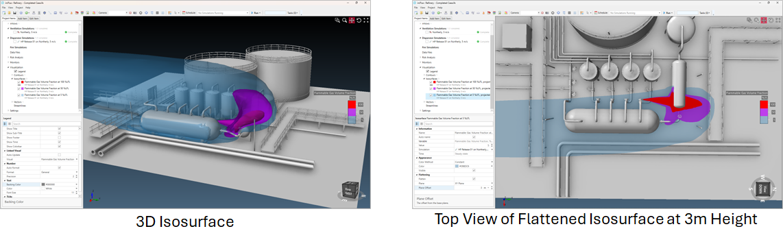
How Flattening Works
Flattening collapses the 3D isosurface onto the chosen plane, preserving the maximum extent in the projection direction. The result is a 2D footprint showing the largest area the isosurface reaches at any point along the plane's normal.
The technique is the visualization equivalent of asking "what is the maximum horizontal extent of this gas cloud?" or "where on the deck would heat flux exceed this value at any height?". The flattened plot answers the question with a single 2D image rather than requiring multiple 3D angles.
How to Flatten an Isosurface
-
Select the isosurface (or risk isosurface) in the project tree.
-
In the property grid, find the Flattening section (indicated below)
-
Tick the Flatten checkbox.
-
Set the Plane to the desired projection plane (XY Plane for a horizontal projection looking down, XZ Plane or YZ Plane for vertical projections).
-
Set the Plane Offset to position the projection plane along the normal direction (for example, an XY Plane offset of "3 m" places the projection plane 3 m above the origin).
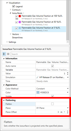
The isosurface re-renders as a flattened projection. The flattening can be toggled on and off without re-running the simulation, since it is a visualization-only operation.
Note: regardless of the Plane Offset, the maximum extent of the isosurface is always displayed. The offset controls only where the projection plane is positioned in the 3D view - it does not change what is collapsed onto it.
When to Use This Option
-
Plan-view deliverables - flattened isosurfaces produce single-image 2D representations suitable for inclusion in reports and PFD-style drawings.
-
Risk-based analysis - a risk-isosurface set to Maximum footprint type gives the worst-case envelope across all simulated scenarios; flattening it presents that envelope as a single plan view.
-
Comparison between cases - flattening to the same plane and offset across multiple simulations or risk data sets makes it easy to compare the spatial extent of the variable between scenarios.
-
Heat flux on horizontal surfaces - for fire simulations, flattening an incident-radiation isosurface to a horizontal plane indicates which areas would, at any height, experience thermal exposure above the threshold.
Scope and Limitations
-
Flattening is a visualization choice. The underlying simulation result is unchanged. Toggling the flatten option does not require recomputation.
-
The flattened projection collapses 3D structure (vertical layering, recirculation pockets) into a 2D footprint. 3D isosurfaces are generally preferred as they indicate the true three-dimensional nature of the visualization; the flattened option is an additional view for specific applications, not a replacement for the 3D view.
-
The plane offset translates the projection plane, not the isosurface itself. Set the offset to put the projection where it is most readable in the 3D view.
See also: Tutorial 6 - Advanced Visualizations, Tutorial 11 - Risk-Based Simulations.