Setting Up HVAC Through-Flow Fan
Through-flow fans exist on offshore and onshore facilities to assist with properly ventilating process decks and other regions.
in:Flux has options to add HVAC, forced inlets, forced outlets, and fans. The following example goes over how to define a through-flow fan for your project.
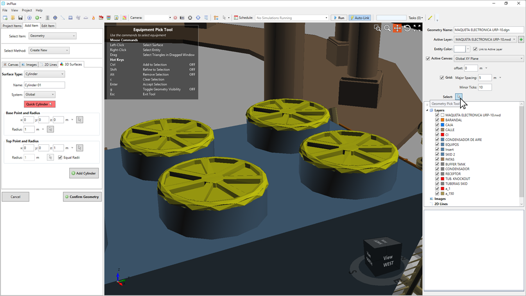
Note that for a through-flow fan to be calculated correctly, no CAD surface can exist behind or under the fan. The image below shows how fans have been explicitly defined in the CAD. It is important that the CAD representing the fan blades, grating, supports, etc are removed so that flow can travel through the fan. If the CAD model has a cap or solid plate over or under the fan, this would also need to be removed or it would hinder flow through the fan. This part of the model can be removed in in:Flux with the CAD Creation Tool's Equipment Selection, shown below selecting the fan geometry. Alternatively, rather than removing the CAD, a porous region may be defined over the geometry items making up the fan so that flow can pass through.
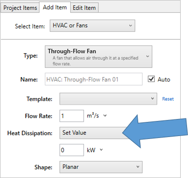
Heat Dissipation
As of version 3.0 a heat source can be added to the through-flow fan. Choosing Set Value allows a kW value to be entered. This can be used to model things such as recirculation of fin-fan heat exchangers.
How to define a Through-Flow Fan:
-
Select HVAC or Fans from the Select Item dropdown menu
-
Choose Through-Flow Fan as the Type
-
Leave the Name as its auto-generated one
-
Set the Flow Rate to "2.0 m3/s" or your known/measured value
-
Leave the Heat Dissipation to None or add a kW value if needed for your project by choosing Set Value.
-
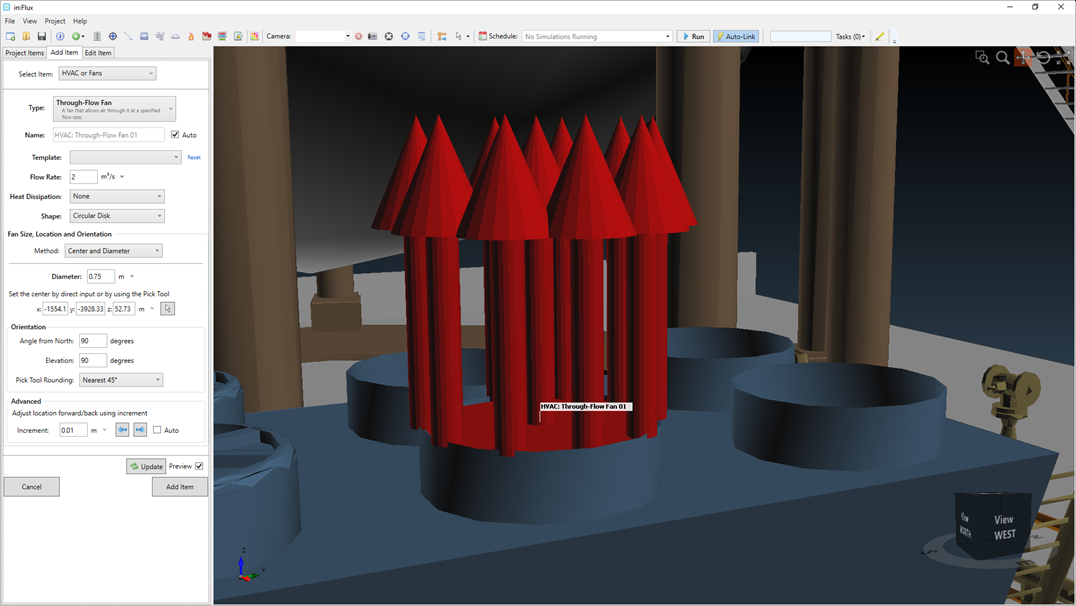
As this example has circular ducts, set the Shape to Circular Disk. You may also opt to use a Planar option to define the shape from selected points for non-circular fans.
-
Ensure that Center and Diameter is selected as the Method.
-
Use the Location and Orientation options as you would for a HP release - using the Pick Tool to select a center point then entering a diameter. For this example, the fan is placed to fit above the duct of the evaporator.
-
Once positioned and oriented as desired, click the Add Item button.
-
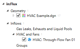
The fan will be added to the Project Items tab under the HVAC and Fans option:
-
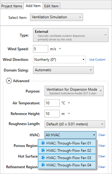
When defining ventilation cases, click the Advanced options and then select the HVAC: Through-Flow Fan 01 from the HVAC dropdown menu. This will add the fan to the ventilation case an
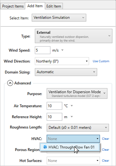
This process can be repeated for adding several fans to a single simulation: