HVAC Definition - Forced Inlet
The gas turbine enclosure has an orange HVAC layer. This section will go over selecting some of the pieces in the HVAC layer as inlets to the simulation meaning air coming INTO the system/domain.
On the northern wall there are four thin vertical boxes. On the lower side of each of these boxes, an inlet will be defined.
Toggle OFF the Building, 2D Lines, and Gas Turbine Enclosure 01.png layer and rotate the model (or use the view cube) to view the underside of the turbines as in Figure 7.
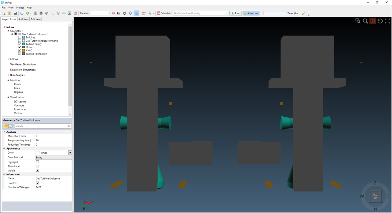
Tutorial 9 - Figure 07 - Viewing the CAD model from beneath with the Building, 2D lines and image layers turned off
Zoom into the bottom right box (north-eastern most box) and right-click on the Inflows text in the Project Items tab and select Add HVAC. Alternatively, you may go to the Add Items tab and select HVAC or Fan from the Select Item dropdown menu.
Continue by using the following steps to add an HVAC inlet to the project:
-
Set the Type of the HVAC to Forced Inlet
-
Leave the name to the automatically defined one
-
Set the Flow Rate as "2.5 m3/s"
-
Select Planar as the Shape for the inlet. HVAC inflows can be defined as either a plane or a circle.
-
Set the Method as From Triangles
-
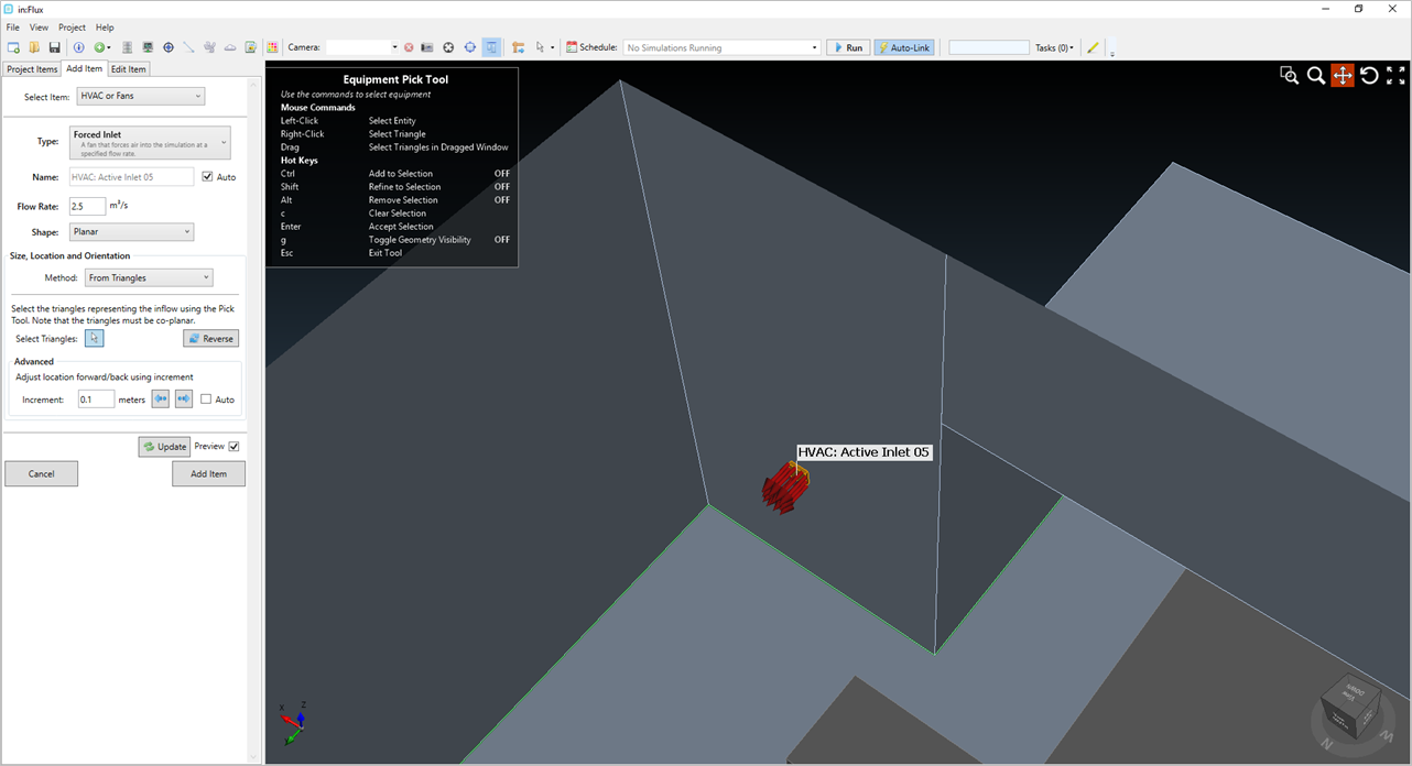
Click the mouse icon next to Select Triangles, this activates the equipment pick tool.
-
Press Ctrl on the keyboard and click once on the underside of the orange box. This will select the triangles used for the inlet boundary condition.
-
Press G on the keyboard to visibly toggle the geometry off and verify that you have only selected the single plane which make up the bottom of the box.
-
Press G again to toggle the geometry back on and click the Preview checkbox in the Add Item panel.
-
Ensure that the arrows for the flow direction are pointed towards the ground, as shown in the figure below.
-
Click the Add Item button.
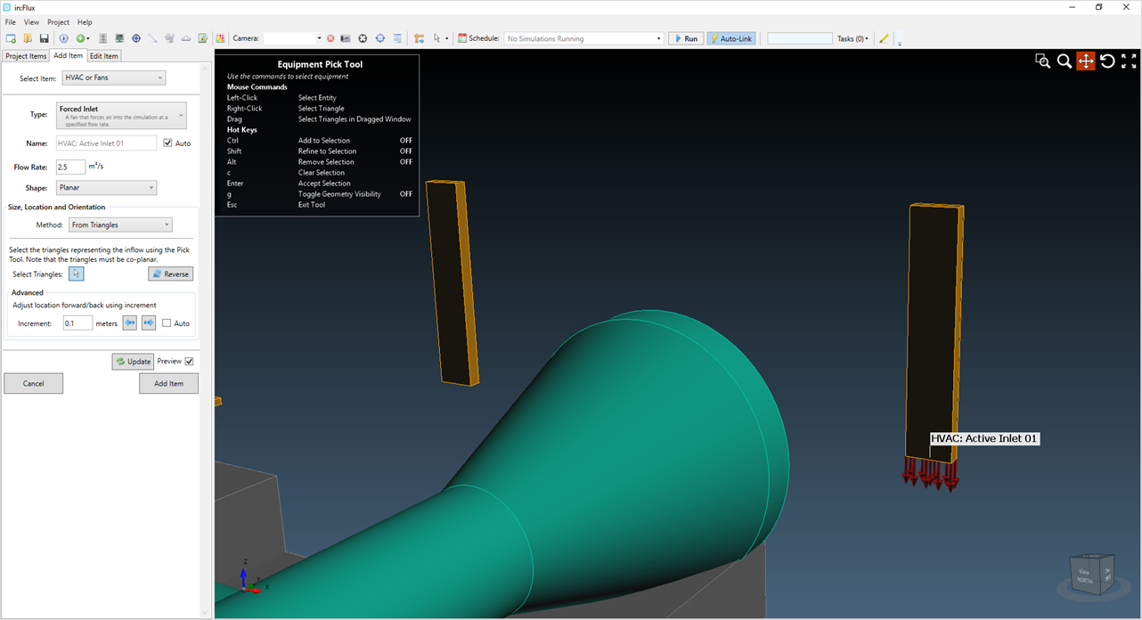
Tutorial 9 - Figure 08 - Location of first HVAC inlet
HVAC and Fans in in:Flux can be defined in one of 4 ways:
-
Shape = Planar, Method = From Triangles - uses the Equipment Pick Tool to select individual planes or triangles as the inflow boundary condition
-
Shape = Planar, Method = From Points - uses the Multi-Pick Tool to draw a shape on an already defined surface. The drawn shape will be used as the inflow boundary condition
-
Shape = Circular Disk, Method = Center and Diameter - creates a circular inflow using the pick tool to select the center point of the disk and the specified diameter
-
Shape = Circular Disk, Method = Three Points - requires three points to be selected within the model, a circular surface is generated with edges touching the three defined points.
Continue by adding a second HVAC inlet to the project using the second method mentioned above:
-
Set the Type of the HVAC to Forced Inlet
-
Leave the name to the automatically defined one
-
Set the Flow Rate as "2.5 m3/s"
-
Select Planar as the Shape for the inlet.
-
Set the Method as From Points
-
Position the 3D window to look at the underside of one of the other orange HVAC boxes
-
Select the Multi-Pick Tool

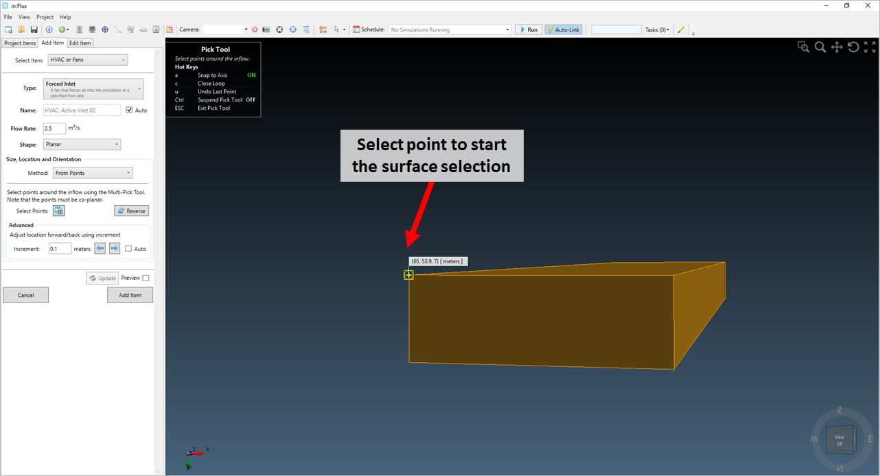
Tutorial 9 - Figure 9 - Using the multi-pick tool to select the first point of the surface to be created for the inlet
-
Click three of the corners of the underside edge of the HVAC box (the pick tool should 'snap' to them as described in the figures below
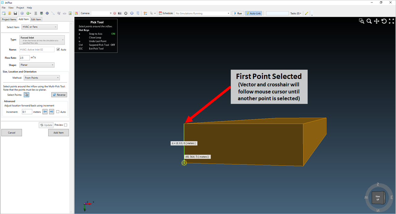
Tutorial 9 - Figure 10 - after the first point is chosen a vector and yellow line will appear and follow the mouse until a second point is selected.
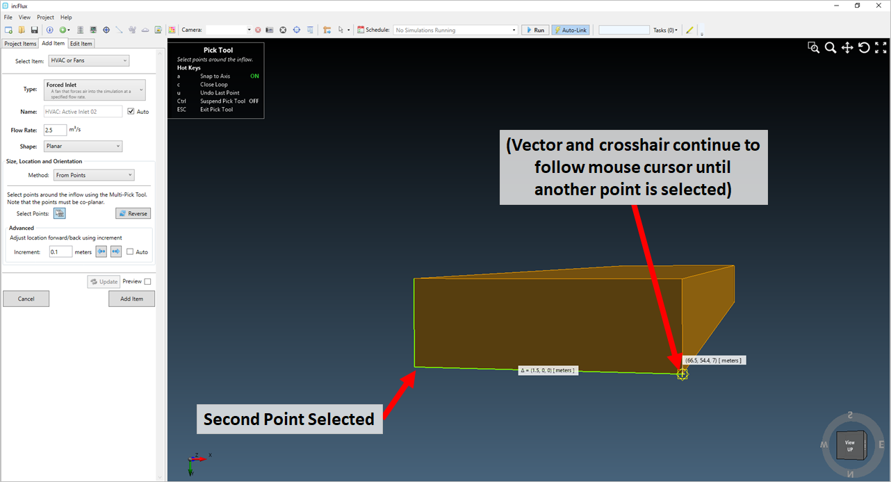
Tutorial 9 - Figure 11 - As points are selected the yellow line tracks connects each point to create the surface of the inflow.
-
To close the drawn box press C on the keyboard
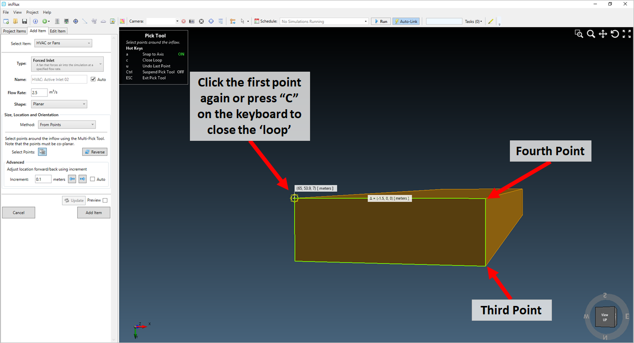
Tutorial 9 - Figure 12 - to close and finish the surface press "C" and the pick tool will close. Alternatively, click the first selected point and press Esc to close the tool
-
-
Click the Preview checkbox and ensure that the direction arrows are pointed towards the ground, as in Figure 13. You may need to press the
 button
to flip direction of the arrows.
button
to flip direction of the arrows.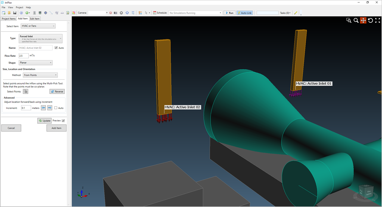
Tutorial 9 - Figure 13 - Viewing that the second inlet condition is pointing in the correct direction - down towards the ground.
-
Click the Add Item button to add the second inlet to the project.
Use one of the above methods to define two more inlets on the underside of the remaining two orange HVAC boxes, each with a flow rate of 2.5m3/s. After adding the four inlets, your window should be similar to the figure below.
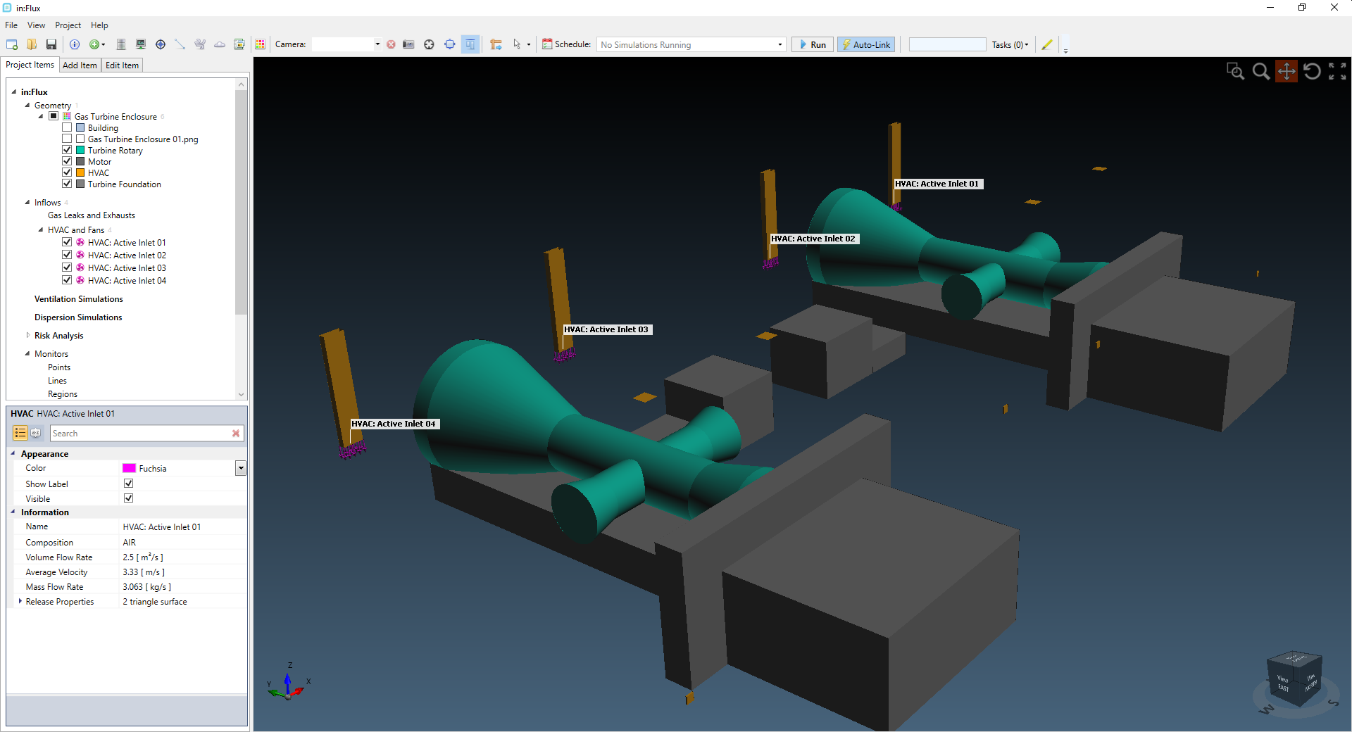
Tutorial 9 - Figure 14 - Showing the four HVAC inlets defined in the project.
On the opposite (southern) wall there are four more square boxes in the HVAC layer, indicated by the blue circles in Figure 15 below. Add an HVAC inlet on inner facing surface for each of the squares. You may turn on the building layer and clip plane to assist in determining the inner facing surface of the square, as shown in Figure 16. Set a flow rate of 2.5m3/s for each of the four HVAC inlets. Once added, your screen should be similar to Figure 17.
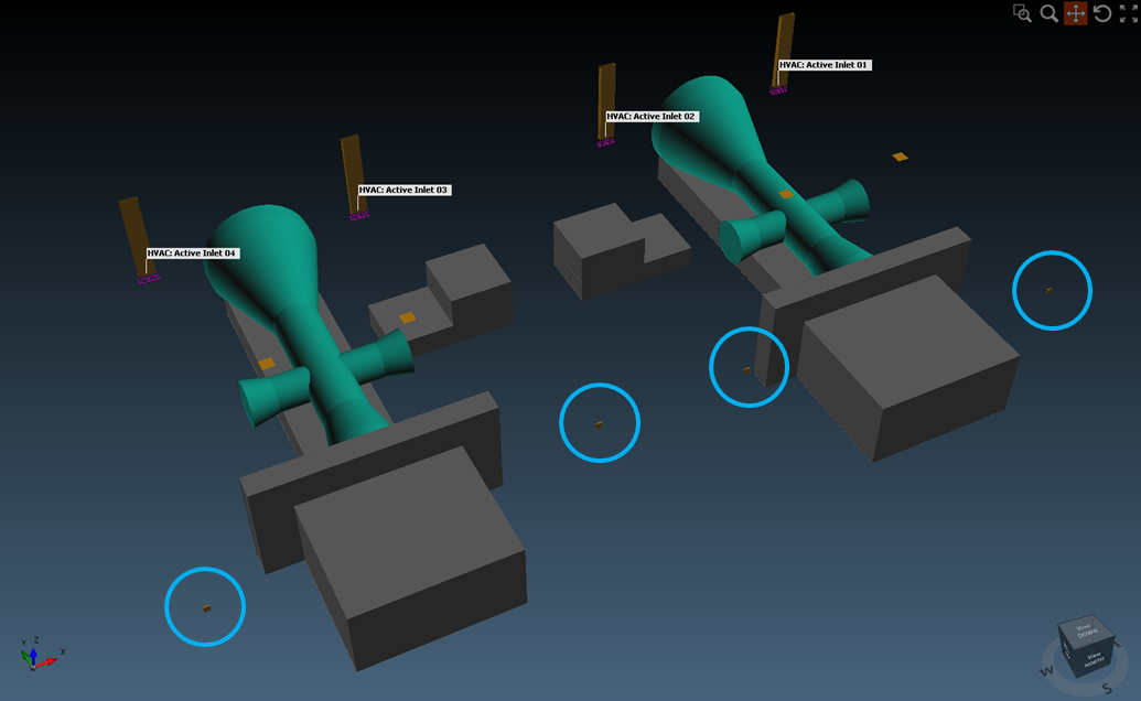
Tutorial 9 - Figure 15 - Location of the last 4 HVAC inlets on the southern wall of the building
Tutorial 9 - Figure 16 - Preview
of the 5th HVAC inlet defined on the wall of the turbine enclosure. The 'from triangles' method was used to select the surface of the square. The Building layer was turned on and a clip plane defined at 14.9m
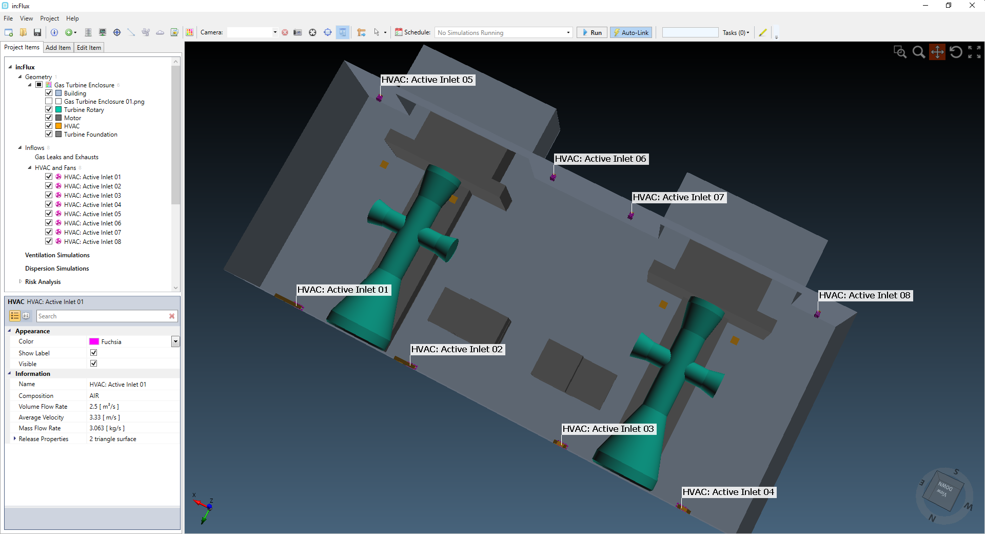
Tutorial 9 - Figure 17 - Showing
all 8 HVAC inlet conditions for the simulation.
You should now have 8 HVAC inlets defined each with a flow rate of 2.5m3/s. Continue to the next section to define the outlet conditions for the simulation.