Maneuvering Within Buildings - Layers and Clip Planes
Many times it is difficult to navigate around or through complex CAD models. One way to help with this issue is to make use of the Clip Plane which is described in Tutorial 6. This can be activated by right-clicking within the 3D window and selecting Define Clip Plane. In the window that appears, click the Activate checkbox and notice how the CAD model is now cut visually in the 3D window, as in the figure below. The visual slice can be set on any plane and at any desired offset.
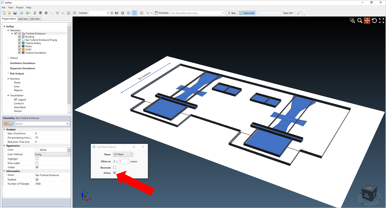
Tutorial 9 - Figure 03 - Activating the Clip Plane in the 3D window
Set the value of the offset as "14.9" and close the window. Once defined you can quickly toggle the clip plane by selecting the  button on the tool bar, as indicated by the red arrow below.
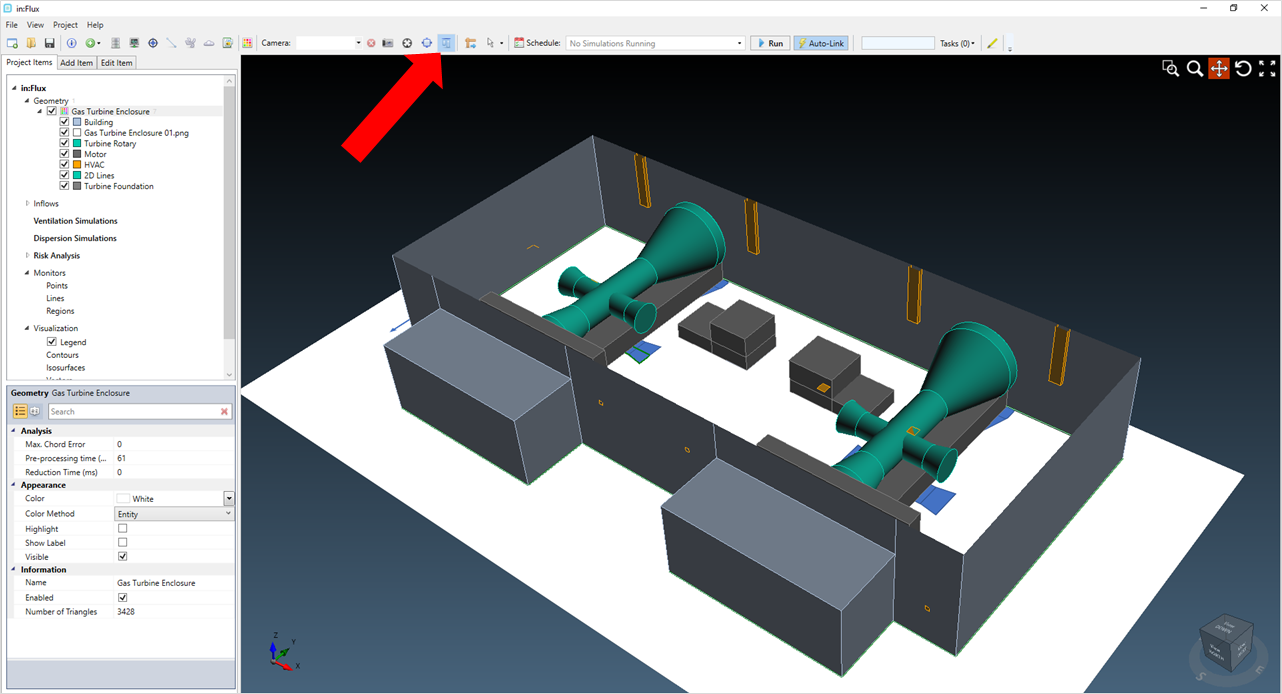
Tutorial 9 - Figure 04 - 3D window after setting the 14.9m offset for the clip plane
In addition to the clip plane, layers can be visually toggled to assist in ease of navigation around the file. For the gas turbine enclosure geometry, click the small triangle next to the geometry name (indicated by the red arrow below). The layers of the file will be shown. Each one of these can be visually turned on or off. This will not affect the simulations. You may also delete individual layers of the model or add new ones in the CAD Creation Tool.
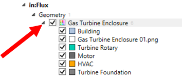
Tutorial 9 - Figure 05 - View the layers of the CAD model
Click the check box next to the gray Building layer, to toggle its visibility. Your 3D window should appear similar to Figure 06 below.
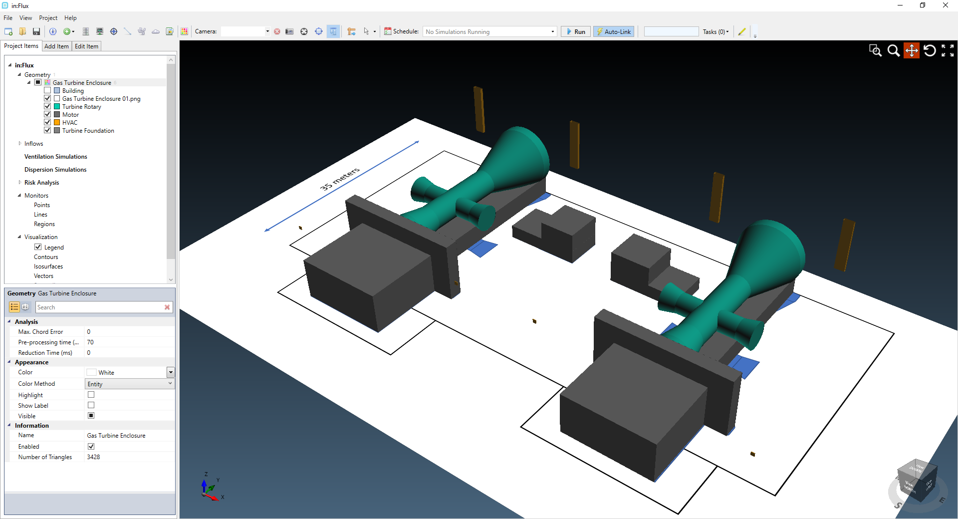
Tutorial 9 - Figure 06 - Toggling the Building layer for the gas turbine enclosure
This tutorial will be using both of the above methods to facilitate working on the project, use whichever method that works best for you.