CAD Creation Tool Guide
The create geometry tool within Detect3D and in:Flux can be accessed via the add items tab or by right clicking the Geometry header in the Project Items Tab and selecting Create New Geometry. This will open a new user interface for editing and creating CAD geometry. For step-by-step instructions for building CAD geometry upon an imported image, see the YouTube links below or the CAD Creation Tutorial..
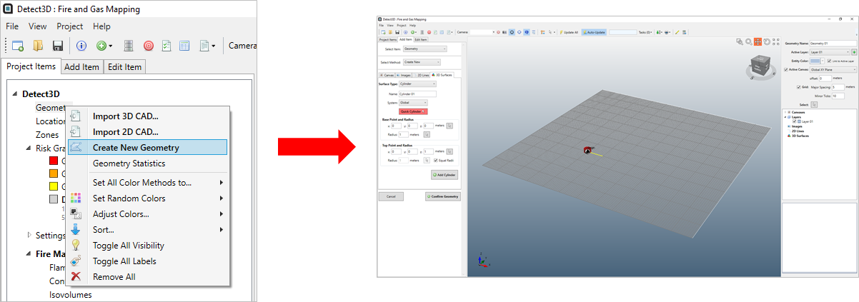
There are 4 tabs on the left panel of create geometry tool which categorize the varying capabilities.
- Canvas - This tab will allow you to define a plane on which you can then draw and create objects on. Canvases need to be defined at the height in which you desire objects.
- Images - Allows you to import images and orient/scale them appropriately for your project. The images can then be used to aide in creating geometries or for visualization purposes.
- 2D Lines - Here you can create 2D shapes (polylines, circles, arcs, etc) which can be used when defining 3D surfaces. Most commonly the polyline is used to draw/outline walls of a facility then extruded in the 3D surfaces tab.
- 3D Surfaces - This tab allows you to add 3D shapes such as cubes, spheres, and cylinders as well as create 3D shapes from 2D lines which you have already defined. The 'Quick' buttons allow for shapes to be made with just 3 clicks of the mouse.
In addition to the CAD Creation Tutorial, please have a look at our YouTube Videos going over building a CAD geometry from an example plot plan. The walk through is in 2 parts and has no audio but provides a detailed explanation of how to go about building CAD models within in:Flux CFD or Detect3D.
CAD Creation Tool - Part 1: https://youtu.be/A5_dGZ8SanI
CAD Creation Tool - Part 2: https://youtu.be/7nRW3iKPwu8
Contents: