Advanced Ventilation Setup with RSTM
As was seen in Tutorial 4, several ventilation cases can be defined at the same time. This also can be applied for ventilation cases using the Reynolds Stress Transport Model (RSTM).
The below steps define 16 ventilation cases. The next section will compare the results using the Batch Image Output Tool.
As with all in:Flux projects, the ground level must be defined first. This is important as it will affect the boundary layer of the simulation.
-
From the Add Items tab choose Ventilation Simulation from the Select Item dropdown menu
-
Ensure the Type of the ventilation is set to External
-
Set the Ground Level Height to "0 meters" by clicking the
 button. The Ground Level section should disappear once this
button is clicked. For offshore projects, the Ground level should be set to the height of the ocean surface.
button. The Ground Level section should disappear once this
button is clicked. For offshore projects, the Ground level should be set to the height of the ocean surface. -
Enter a Wind Speed of "10" meters per second
-
Click the Wind Direction dropdown menu and while holding down Shift on your keyboard click the last listing North-Westerly (315°) to select ALL 8 wind directions. A blue highlight of the text, as shown below, will indicate that all options have been selected. Click off the dropdown menu to verify the selection.
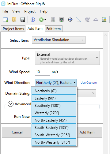
Tutorial 10 - Figure 02 - Selection of all available wind directions
-
Leave the Domain Sizing as Automatic.
-
Click the Advanced arrow (
 ) to expand the panel and in the Purpose dropdown menu select Helideck Turbulence as shown in the figure below. Leave the other options as their default values.
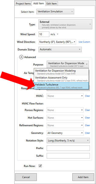
Tutorial 10 - Figure 03 - Setting the ventilation simulation to use the RSTM for Helideck Turbulence analyses
-
Ensure that the Run Now checkbox is selected and click the Add Item button.
-
Repeat steps 1 through 8 above to define another 8 cases with a "15 m/s" wind speed. As all the other setup options are the same, only the wind speed value needs to be set.
Return to the Project Items tab to confirm that there are now 16 ventilation simulations in the project. Your window should appear similar to Figure 04 below.
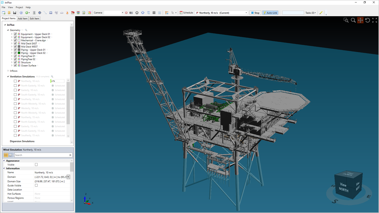
Tutorial 4 - Figure 04 - Showing 16 new ventilation simulations in the project items tab
Each ventilation case using the RSTM will have a helicopter icon ( ) next to it. Normal ventilations with the SST turbulence model (those
in Tutorials 1 through 9) will have a windsock icon (
) next to it. Normal ventilations with the SST turbulence model (those
in Tutorials 1 through 9) will have a windsock icon ( ).
).
Continue to the next section view information about the RSTM calculation process.