Setting Up Plausible Detector Locations
For the gas detector optimization to be successful, inputs for plausible gas detector locations need to be defined.
The locations allow you to apply your own knowledge and judgment on where good locations are for gas detectors as the software does not have information such as wiring, ease of maintenance or past experiences.
The first part of this section goes over adding a series of monitor points and monitor lines. At the end of the section a file is provided so that you may import monitors to match the optimization results for this tutorial.
Adding Monitor Points
As discussed in Tutorial 3, you may add an array of Monitor Points using the Line Spaced, Area Spaced, or Volume Spaced options. For this tutorial the line-spaced option will be used to define a series of monitor points to act as plausible locations for point gas detectors:
-
Open the Tutorial 12.ifx file. The file has 120 dispersion cases simulated for an example facility and references the data files created in Tutorial 11.
-
Zoom into the upper deck indicated in Figure 1 below and select Monitor Points from the Select Items option in the Add Items Tab
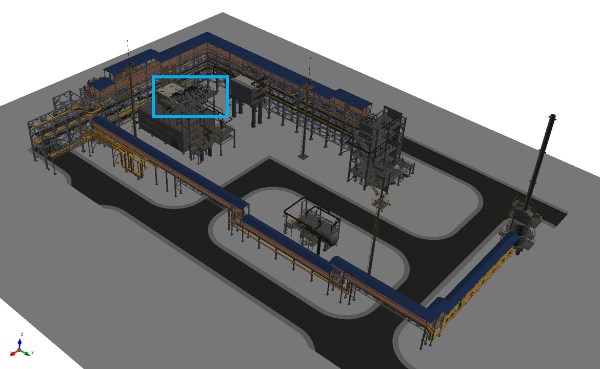
Tutorial 12 - Figure 1 - location of where to add monitor points to the project
-
Leave the Name as the automatically defined one
-
Change the Method to Line Spaced and add 5 monitor points at the upper deck next to the control boxes as shown in Figure 2, alternatively you may enter the following:
-
For the First Point enter the coordinate ( 57, 33.3, 16 )
-
For the Second Point enter the coordinate ( 57, 29.7, 16 )
-
-
Set the # Points as 5.
-
Next to the Group dropdown menu press the plus icon (
 ) to define a new group of monitors. The monitor groups can be
used to organize and manage monitors in the project. The name of the new group will automatically be set to Group 02, but this will be changed later.
) to define a new group of monitors. The monitor groups can be
used to organize and manage monitors in the project. The name of the new group will automatically be set to Group 02, but this will be changed later. -
Set the Purpose to Detector Optimization. This tells in:Flux not to store simulation data but to use the monitor point location with risk data sets and detector optimization which significantly reduces project file sizes. All monitors in this tutorial should be added with the Detector Optimization purpose.
-
Click Add Item to add the 5 monitors to the project.
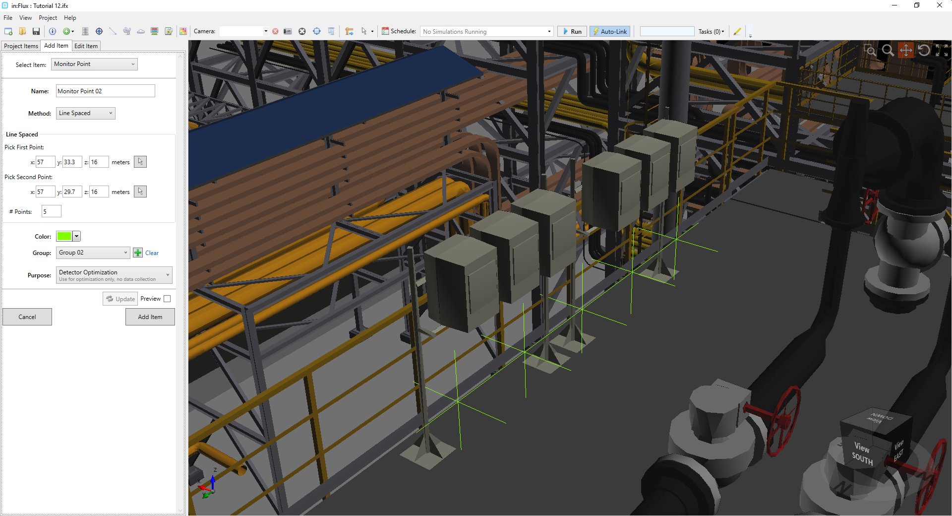
Tutorial 12 - Figure 2 - First five monitor points added to the project
Repeat Steps 2 -8 by adding a few more monitor points on the mid-level deck to Group 02. The more monitors added the better the chances of the optimization improving the layout. The below image has 129 monitor points defined along structural members of the facility. At the end of this section an in:Flux file is provided so you can import the monitor points shown in Figure 3.
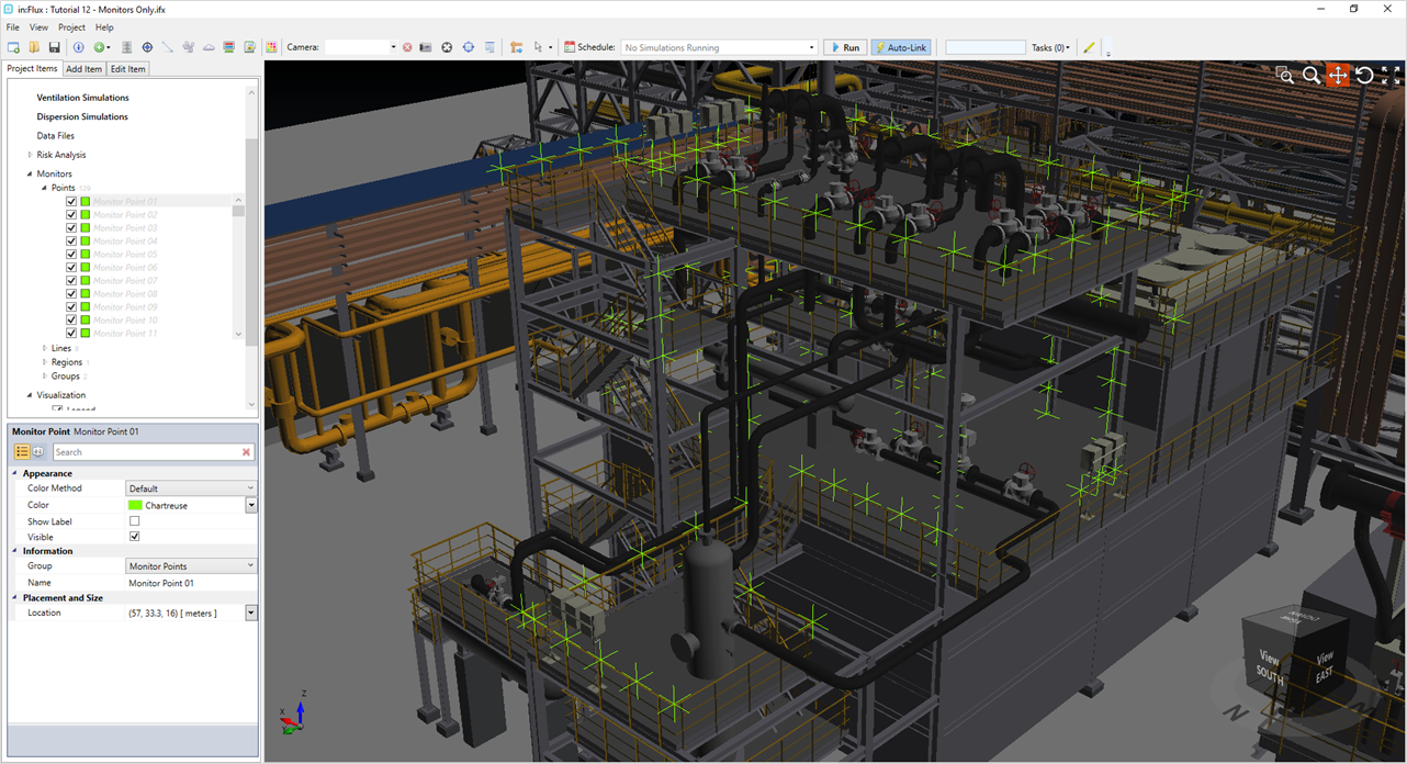
Tutorial 12 - Figure 3 - Screenshot with monitor points defined
Adding Monitor Lines
In addition to monitor points, monitor lines can be added as open-path gas detectors. When optimizing, the LEL.m alarm level can be set.
Add a couple monitor lines to the project:
-
Click the Add Item tab and select Monitor Line from the dropdown menu
-
Leave the Name as the default name.
-
Enter the following values for the First Point: ( 43.8, 34.72, 10.5 )
-
For the Second Point, enter (43.8, 16.91, 10.5 )
-
Click the plus icon (
 ) to create a new monitor group, the group with automatically be named Group 03 but will be
changed later
) to create a new monitor group, the group with automatically be named Group 03 but will be
changed later -
Set the Purpose to Detector Optimization.
-
Preview the monitor line and ensure it is in a location similar to Figure 4 below and click the Add Item button
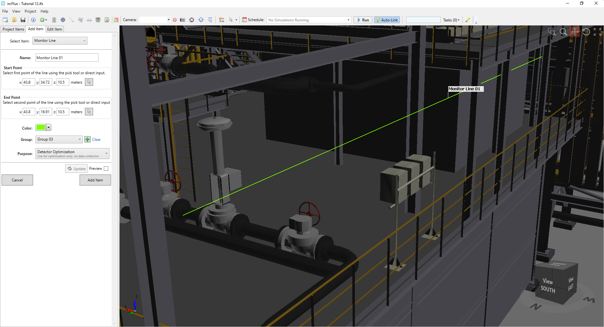
Tutorial 12 - Figure 4 - Position and setup for the first monitor line added to the project. The line has been changed to a blue color to help distinguish it from the background
Repeat Steps 1 -7 above adding at least four more monitor lines assigned to Group 03 around the perimeter of the upper and mid-deck levels similar to the figure below.
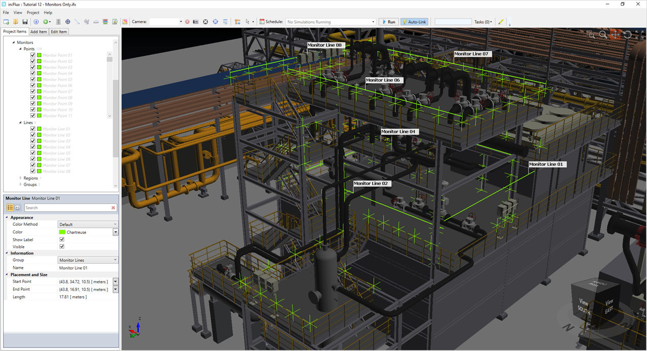
Tutorial 12 - Figure 5 - Tutorial 12 file with monitors added to the project
Importing Monitor Points from another .ifx file
Rather than individually define each of the monitors above, you may opt to merge the downloaded Tutorial 12 - Monitors Only.ifx (4 MB) file with your current project. The merge capability allows you to extract monitors and other project items from one in:Flux file to the currently open project.
Download the Tutorial 12 - Monitors Only.ifx file mentioned at the beginning of the tutorial to import the monitors to your project:
-
To have your optimization results match this tutorial, delete all the existing monitor points and monitors lines.
-
With the Tutorial 12.ifx file open, go to the File Menu and select
 Merge Project
 -
In the window that appears, navigate to the Tutorial 12 - Monitors Only.ifx file and click Open
-
The window that appears will have a list of checkboxes for what project items to import, select the Monitor Points and Monitor Lines checkboxes
-
Click Merge

This will then import the 135 monitor points and 8 monitor lines from the ifx file to your current project. Ensure that the Purpose of the monitor points and lines have been set to Detector Optimization. If not, right click on the Points or Lines text in the Project Items Tab, shown below, and choose Set All Monitor Purpose to Detector Optimization. The points and lines may still have gray text, but this is okay for use with optimization.
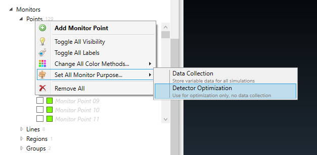
Tutorial 12 - Figure 6 - Setting all Monitor Points to have a Purpose of Detector Optimization. Same can be done with Monitor Lines
Proceed to the next section to setup the Monitor Groups.