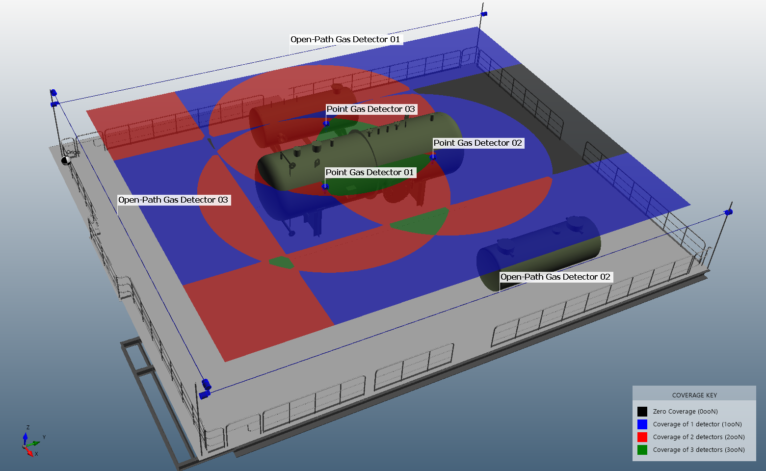
Tutorial 2 - Gas Detector Project

Most mapping projects require analysis of both flame and gas detectors. Detect3D generates a three-dimensional assessment of point and open-path gas detectors using the geographic method for gas mapping. The goal of the analysis is to optimize placement of gas detectors to reduce the spherical gas cloud from going undetected. The size of the gas cloud is typically scaled on the level of congestion in the analysis region.
Detect3D generates a “field of influence” (FOI) for each gas detector added to the project; that is, if the center of the gas cloud is located within the FOI, the detector will go into alarm. Follow this link for more information on the gas mapping coverage calculation.
-
For point gas detectors, the FOI will directly correspond to the size of the spherical gas cloud – a 5m diameter gas cloud will lead to a 5m FOI for the point gas detector, centered on the detector itself. This is true regardless of the manufacturer, make, or alarm setting of the detector.
-
The generation of the FOI for open-path gas detectors is slightly more complex, as the spherical gas cloud must intersect the beam between the transmitter and receiver by a certain length before the alarm is triggered. The FOI for an open-path gas detector resembles a rounded cylinder with the center line on the beam. The diameter of the FOI is slightly less than the diameter of the gas cloud.
This tutorial will cover adding point and open-path gas detectors to a project. Contours will be used to visualize coverage results within the defined zone.
Learning objects for this tutorial include:
-
How to place a point gas detector
-
How to place an open-path gas detector
-
How to add vertical contours
Files used in this tutorial:
-
Simple Module.obj (2.2 MB)
The CAD model is located in the tutorials folder of the Detect3D directory (usually C:\Program Files\Detect3D\Tutorials depending on the folder chosen during installation). Alternatively, you can load the "Simple Module (.obj)" by selecting it from the Load Sample Geometries option in the Help Menu.
Contents of Tutorial 2: