Ventilation Definition
in:Flux only needs inputs of direction and speed to run a ventilation calculation.
The cardinal directions in:Flux uses are as the following figure when looking at the X, Y, and Z axes located at the bottom left of the 3D window.
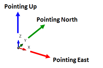
Tutorial 1 - Figure 04 - Indication of North and East directions based on X, Y, and Z axes
At the bottom right of the 3D window a View Cube, shown below, exists which also indicates the current direction the 3D window is pointing. You can click a side, edge, or corner of the cube to change the view of the 3D window to the clicked direction. The visibility of the View Cube can be changed in the application settings in the Project Items Tab.
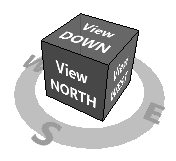
Tutorial 1 - Figure 05 - Image of the View Cube found at the bottom right of the 3D window.
For this tutorial a westerly wind of 5 m/s will be simulated.
To setup the ventilation:
-
Click the Add Item Tab and choose Ventilation Simulation as the Selected Item as shown below.
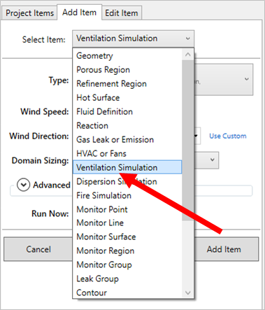
Tutorial 1 - Figure 06 - Selection of Ventilation Simulation from the Selected Item dropdown menu.
-
Set the Type as External
-
Enter a value of "5" for the Wind Speed.
-
Select Westerly (270°) as the Wind Direction.
-
TIP - click the Westerly (270°) wind direction text once, and then click once outside of the dropdown menu to choose a single wind direction. Note that the cardinal direction is where the wind is blowing FROM.
-
-
Select Automatic as the Domain Sizing. It is recommended that Automatic is always used for domain sizing.
-
As this is the first simulation for the project, the ground level needs to be defined. This setting will then be used for all other ventilation simulations in the project. For this tutorial, set the Ground Level to "0" meters.
-
Click the Confirm button
 to set the ground level. This value can be changed from the Project Menu after it has been set. The panel will also disappear after the ground level is set.
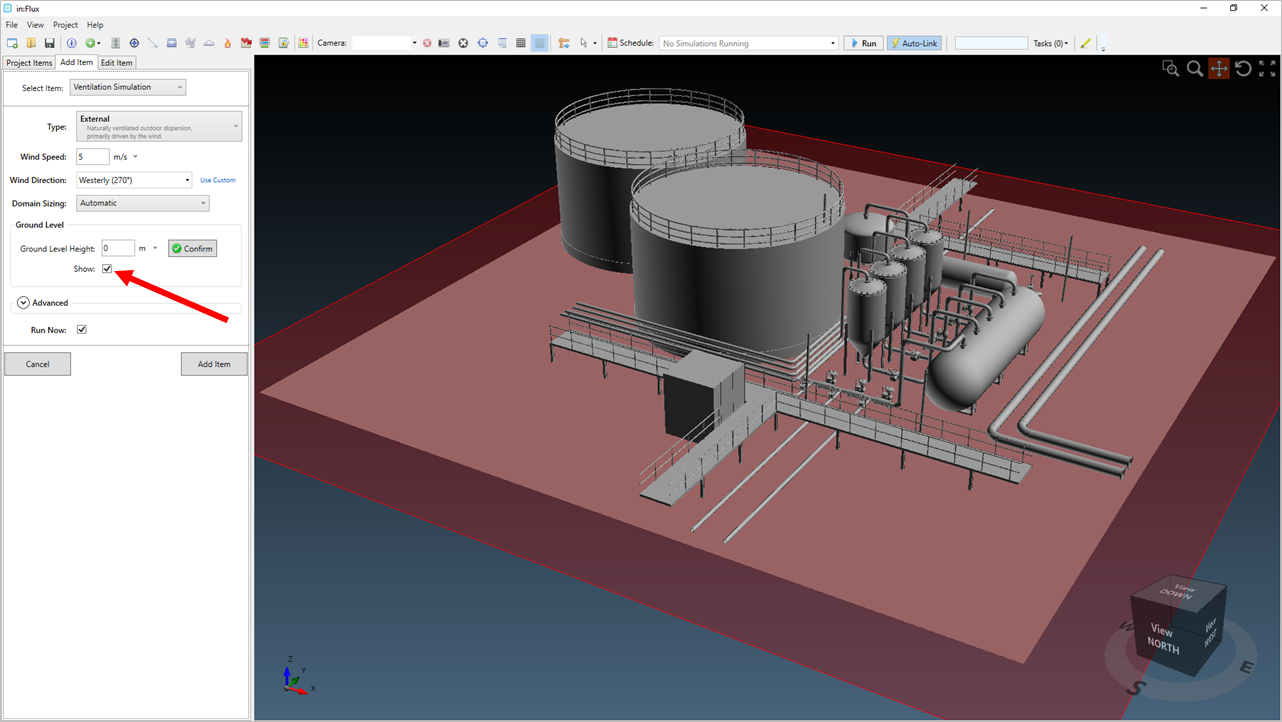
Tutorial 1 - Figure 07 - Selection of the ground level height
-
-
Leave the Advanced section as-is for now. The features here (air temperature, reference height, roughness length, HVAC sources, included geometry and some other options) are discussed in the Advanced Capabilities section.
-
Make sure the Run Now checkbox is selected. Doing this is helpful in automating your in:Flux workflow. With the Run Now check box selected, the simulation will be added to the Simulation Scheduler when the Add Item button is clicked. This will be discussed more in Tutorial 4. With Run Now checked will tell in:Flux to start the calculation for our single ventilation case upon clicking the Add Item button .
-
Press the Add Item Button
Immediately after clicking the Add Item button, you should be notified by the message in the left hand panel that the simulation has been added to the project.
![]()
Tutorial 1 - Figure 08 - Notification message of the simulation being added to the project which appears under the Add Item Button
Congratulations! You have already set up your first CFD simulation with in:Flux. However, setting up a simulation and adding it to the project does not mean the calculation has completed. After clicking Add Item the simulation will first have to be initialized, and then the calculation needs to solve the different variables of the Navier-Stokes equations (transport equations) before it will be completed.
Continue to the next section to view information about the currently running calculation.